NO-TITLE-PAGE
sinilink relays module
This is a ESP8285H16 based board with an onboard MOSFET controlled output delivering the input voltage.
It is sold as a “relay” board actually not having a relay but a MOSFET to switch the negative output pin. It can be supplied by 5V to 36V DC.
The espressif module uses the same processor from the EPS8266 and includes an integrated 2 MByte Flash rom on the chip.
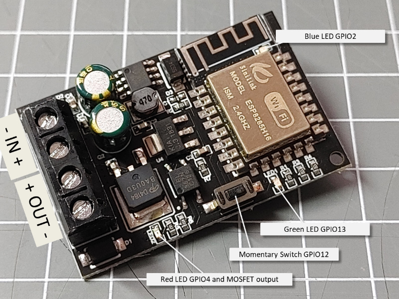
Pins in use
GPIO2(D4) - The ESP8285 module has a blue LED that can be switched on by pulling the GPIO2(D4) to LOW.
GPIO4(D2) - The red LED and the MOSFET are activated by a HIGH signal on the GPIO4(D2) pin.
GPIO13(D7) - The green LED is activated by a HIGH signal on the GPIO13(D7) pin.
GPIO12(D6) - The momentary switch pulls the GPIO12(D6) to LOW.
Setup and Upload
The ESP8285 modules are supported as Generic ESP8285 Modules by the Arduino environment and can use the 2MByte flash size with 1MByte filesystem.
The full standard example can be flashed.
Flashing the first time
As there is no USB bridge available a external USB adapter has to be used for flashing the firmware for the first time.
I manages this by attaching the 5 signals GND, 3V3, TX and RX to a USB-Serial adapter. The GPIO0 must be pulled to GND while powering up the board.
After flashing a first firmware the OTA Update can be used.