ESP32 Azure IoT Kit
This is a ESP32 based board based on ESP-WROVER-B module designed by espressif and Microsoft as a reference IoT Kit Azure. It is no more manufactured.
This is Work in progress
This board is no longer manufactured but in case you have it arround here you find details.
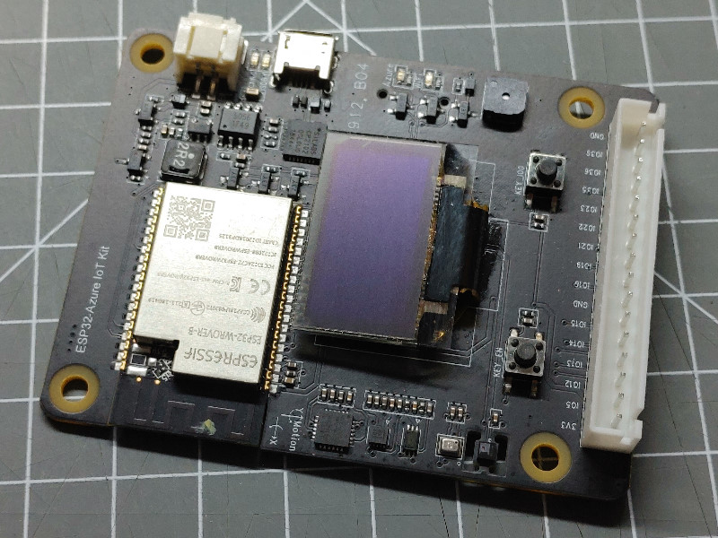
The ESP32 based board is equipped with some interesting sensors, buttons, leds and a display and can easily be used for development.
I2C bus
The sensors and the display are reachable on the I2C bus using the signals (sda=25, scl=26).
The env.json configuration includes these settings in the Device Element.
| I2c Address | Sensor |
|---|---|
| 0x0e | Magnetometer MAG3110 |
| 0x23 | Ambient Light Sensor BH1750 |
| 0x3c | Display SSD1306 |
| 0x5f | Humidity and Temperature Sensor HTS221 |
| 0x68 | (RTC,DS1307) |
| 0x6d | Barometer FBM320 |
LEDs
There are 2 green LEDs available:
- The LED labeled “Azure” is available on GPIO 33.
- The LED labeled “WiFi” is available on GPIO 32.
Both LEDs are not connected directyl but through a small MOSFET that inverts the signal. The LEDs will light up when the signal level is HIGH.
{
  "digitalout": {
    "led-azure": {
      "value": "1",
      "title": "digitalout/led-azure",
      "pin": "33"
    },
    "led-wifi": {
      "value": "1",
      "title": "digitalout/led-wifi",
      "pin": "32"
    }
  }
}
Input Buttons
There are 2 buttons available
- The left button is bound to the RESET of the CPU chip.
- The right button is available on GPIO pin 0.
The right button is pulling the input level to LOW when pressed.
The env.json configuration includes the settings using the Digitalin Element.
Buzzer
The buzzer on board is connected to pin 27. This is a passive speaker that can be used with the Tone Element to make some noise.
The env.json configuration includes these settings in the Tone Element.
Ambient Light Sensor BH1750
This sensor is available on the i2c bus on address 0x23 (default).
In the description of the BH1750 Element you can find more details.
The env.json configuration includes these settings in the BH1750 Element.
Motion Sensor MPU6050
3-axis gyroscope, 3-axis accelerometer
This sensor is available on the i2c bus on address 0x68.
- https://invensense.tdk.com/products/motion-tracking/6-axis/mpu-6050/
- https://invensense.tdk.com/wp-content/uploads/2015/02/MPU-6000-Datasheet1.pdf
Barometer FBM320
0x6D
Magnetometer MAG3110
0x0E
Humidity and Temperature Sensor HTS221
0x5F
Battery charging
SD Card
The SD card is available at the standard SPI bus of ESP32. The
SD Card Element can be used to extend the filesystem
and to mount the sd card file system on the /sd folder.
| function | ESP32 pin |
|---|---|
| CS | GPIO13 |
| SPI-bus | VSPI |
Device Configuration
This is a device specific configuration for this board :
{
  "device": {
    "0": {
      "name": "azurekit",
      "title": "Azure Kit",
      "description": "ESP32 Azure IoT Kit by Espressif",
      "button": "0",
      "led": "33",
      "i2c-SDA": "25",
      "i2c-SCL": "26",
      "i2c-frequency": "50000"
    }
  },
  "ota": {
    "0": {
      "port": 8266,
      "passwd": "123"
    }
  },
  "diag": {
    "0": {}
  },
  "ntptime": {
    "on": {
      "zone": "CET-1CEST,M3.5.0,M10.5.0/3"
    }
  },
  "displayssd1306": {
    "0": {
      "address": "60",
      "xresetpin": "D6",
      "brightness": "80",
      "xrotation": 90,
      "width": 128,
      "height": 64
    }
  },

  "digitalin": {
    "key": {
      "pin": "0"
    }
  },

  "tone": {
    "on": {
      "pin": "27",
      "tones": "fifth:d=4,o=4,b=80:8p,8g,8g,8g,2d#,8p,8f,8f,8f,1d"
    }
  }

}
ESP32 WROVER Module
Compile with
OLED Display
SSD1306
-
0x3c: (SH1106,SSD1306,SSD1309)
-
The SSD1306 based display requires a reset line for some cases but the RST signal is not connected to any GPIO.
https://forum.arduino.cc/t/how-to-best-configure-esp32-arduino-vs-code-debug/698140
https://www.esp32.com/viewtopic.php?t=23393
See also
-
https://www.digikey.de/de/products/detail/espressif-systems/ESP32-AZURE-IOT-KIT/10259357
-
https://www.espressif.com/en/products/devkits/esp32-azure-kit/resources
-
https://docs.microsoft.com/en-us/samples/azure-samples/esp32-iot-devkit-get-started/sample/
-
https://buildazure.com/esp32-azure-iot-kit-dev-board-espressif/
-
https://github.com/espressif/esp-iot-solution/blob/master/examples/esp32_azure_iot_kit/readme_en.md
https://github.com/lzyms/ESP32IoTCentral
https://github.com/ewertons/esp32-azureiotkit-sensors
https://iotexpert.com/debugging-ssd1306-display-problems/
Microsoft Tutorial: Connect an ESPRESSIF ESP32-Azure IoT Kit to IoT Hub