CORE-ESP32C3 development board
The CORE-ESP32 core board is based on Espressif ESP32-C3 SoC that fits good on a breadboard and has the option for a LCD + digital joystick shield on top. The ESP32-C3 variant is supported by the HomeDing library.
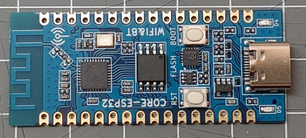
The CORE-ESP32 core board is based on Espressif ESP32-C3 SoC.
- ESP32-C3 processor
- 4 MByte Flash memory in DIO mode
- This is a small board 21mm * 51mm that fits good on breadboards.
- 2 LEDs
- Reset button
- BOOT button
- 2.4G PCB onboard antenna
The CORE-ESP32 board is labeled with luatos.com
Arduino Board Configuration
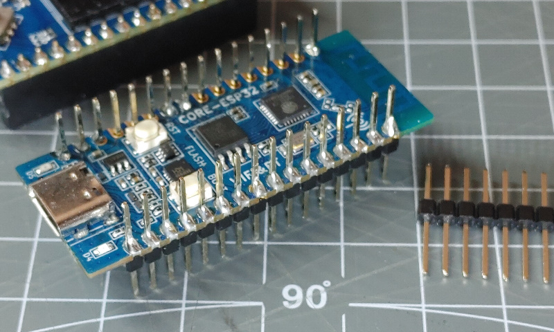
There are 2 main board variants that differ in the implementation of the USB port.
- One variant has an onboard CH343 USB to serial adapter.
- Second variant exposes the USB port of the ESP32-C3 directly.
The ESP32C3 Dev Module (esp32) can be used with the following settings:
- JTAG Adapter: Disbled
- USB CDC On Boot: Disbled for version with CH343 USB adapter
- USB CDC On Boot: Enabled for version with direct USB connection
- Partition Scheme: Default 4MB with spiffs (1.2MB APP/1.5MB SPIFFS)
- CPU Frequency: 160MHz
- Flash Mode: DIO
- Flash Frequency: 80 MHz
- Flash Size: 4MByte (32Mbit)
- Upload Speed: 921600
- Core Debug Level: None
- Erase All Flash: Disabled
Main Board components
The following components are already on-board:
- 4MB single channel SPI FLASH with 2 data lines.
Important: Be sure to flash in DIO mode. QIO doesn’t work. - GPIO12: LED D4 (right to USB)
- GPIO13: LED D5 (left to USB)
- RST: RST Button
- GPIO09: Boot Button
The SPI bus is available and also used by the LCD display.
- GPIO02: SPI-SCK
- GPIO03: SPI-MOSI
- GPIO10: SPI-MISO
- GPIO07: SPI-CS
The I2C bus is mentioned in the manual but not labeled on board:
- GPIO04: I2C-SDA
- GPIO05: I2C-SCL
Board configuration
The following env.json configuration can be used for this board:
{
"device": {
"0": {
"name": "corec3",
"title": "CORE-ESP32C3",
"description": "ESP32-C3 based dev board.",
"button": "9",
"led": "12",
"i2c-scl": "5",
"i2c-sda": "4"
}
},
"digitalout": {
"ledD4": { "pin": "12" },
"ledD5": { "pin": "13" }
}
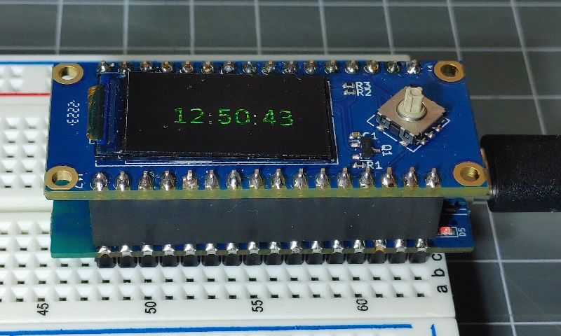
}LCD + Digital Joystick Shield
There is a TFT display and a digital joystick shield available that can be stacked upon the CPU board.
It offers a 0.96 inch display with 80*160 pixels and 262K Color based on the ST7735S driver chip. The background lightning is not adjustable and always on.
The Boot and Reset buttons are not reachable any more after mounting this board.
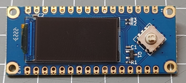
| key | GPIO pin |
|---|---|
| down | GPIO13 |
| left | GPIO5 |
| up | GPIO8 |
| right | GPIO9 |
| press | GPIO4 |
The down key conflicts with the on-board LED that must not used as digital output when the shield is used.
Shield configuration
The following configuration can be used for the Shield:
{
  "DisplayST7735": {
    "0": {
      "description": "Display",
      "loglevel": 2,
      "width": "80",
      "height": "160",
      "colOffset": 26,
      "rowOffset": 1,

      "busmode": "spi",
      "spiClk": 2,
      "spiMosi": 3,
      "resetPin": 10,
      "spiDC": 6,
      "spiCS": 7,
      "rotation": 270
    }
  },
  "digitalin": {
    "right": { "pin":  "9", "invert": "1", "pullup": 1 },
    "up":    { "pin":  "8", "invert": "1", "pullup": 1 },
    "left":  { "pin":  "5", "invert": "1", "pullup": 1 },
    "down":  { "pin": "13", "invert": "1", "pullup": 1 },
    "press": { "pin":  "4", "invert": "1", "pullup": 1 }
  }
}
Pictures
See also
- https://luatos.com/t/esp32c3
- https://wiki.luatos.com/chips/esp32c3/board.html
- luatos wiki: https://wiki.luatos.com
- luatos code: https://gitee.com/dreamcmi/LuatOS-ESP32
- https://hackaday.com/2021/02/08/hands-on-the-risc-v-esp32-c3-will-be-your-new-esp8266/
- https://gitee.com/wendal