Board ESP8266 ESP-01
The ESP-01 is the cheapest bare minimum ESP8266 board available. The connector only supports few GPIO pins but it is small and enough for simple sensors and relay appliances. Only 2-4 GPIO signals can be used. There are variants of this board with different antenna and different flash sizes.
The ESP-01 and ESP-01S modules contain a ESP8266 MCU and a up to 1 MByte flash memory chip.
It is the cheapest available board with the ESP8266 and comes with a standard male adaptor.
Overview table
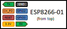
| Connector | Feature |
|---|---|
| TX | Serial output, programming |
| CH_PD | Chip Enable. 10k to VCC |
| Reset | Reset |
| 3.3V | Power supply, needs >= 250mA. |
| GND | reset |
| GPIO2(D4) | OUTPUT, see below |
| GPIO0(D3) | OUTPUT, see below (flash) |
| RX | Serial input, programming |
| Reset | reset |
The 8 pin connector is not usable to place the chip on a solderless breadboard directly but there are adapters available.
There are multiple versions of the ESP-01 board available. In the early days also 512kByte flash memory versions have been available now most of them come with 1 MByte of flash memory. The ESP-01S has a slightly different wiring regarding the LED and a different layout of the PCB antenna ans also comes with 1MByte of flash memory.
ESP-01 LEDs
The original version of the ESP-01 board has 2 LEDs:
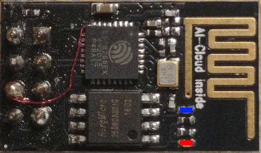
- The red LED is connected to the 3.3V Power supply and lights up constantly.
- The blue LED is connected to the Serial output pin and lights up when data is sent. When not using the TX Serial output the pin and LED can be used as a digital output too.
There have been critics about these 2 LEDs and some recommend to unsolder them e.g. to save power for battery driven solutions.
ESP-01S LEDs
This board is a newer version that
- 1Mbyte of flash memory.
- No power LED
- Blue LED on GPIO2(D4)
Self-Made Adaptors
With some soldering and a USB-to-Serial adapter you can build your own adapter board:
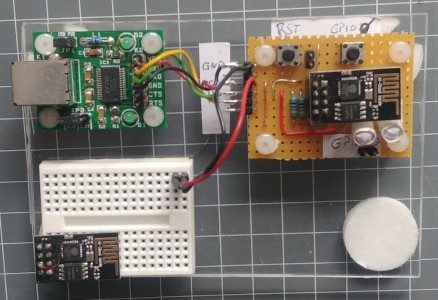
Some of the USB Adapters like the on I use also have a 3.3 V regulator available, but they usually so not offer much current.
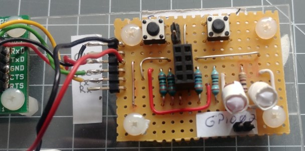
Be sure to add a reset (RST) and flash GPIO0(D3) button with 10k resistor to VCC and button to GND.
The 3 LEDs show the actual level of GPIO0(D3) and GPIO2(D4).
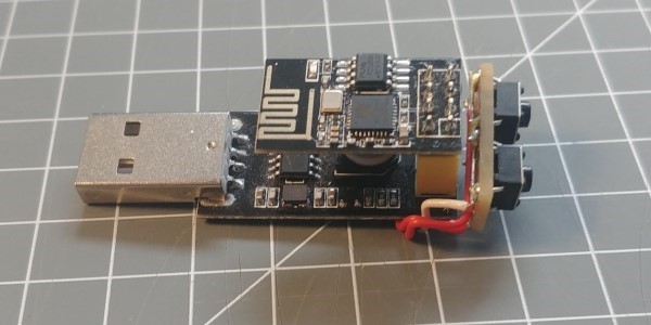
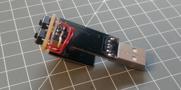
Another idea is to use a ESP01 USB adapter and add the reset (RST) and flash GPIO0(D3) buttons as you can see here.
Minimum adapter
The minimum wiring to use (run) this board is to have the following external wiring:
- pull up CH_PD with 10k to VCC
- pull up RST with 10k to VCC
- connect 3.3V and GND to power supply
GPIO 0
This pin has to be high while booting or resetting the chip when you like to start the regular uploaded program. After starting the program you can use it for input and output.
For example attaching a led with resistor to ground will prohibit starting because the level of the pin is pulled to low. It is better to design all the io functionality using a high level for the inactive state and have a resistor in place to pull the default level to high.
GPIO0 as Momentary input
A momentary button that pulls the GPIO0 down to ground when pressed.
This is one of the often-found wiring for the GPIO0 pin because it is possible to start uploading a new program after resetting the chip while pushing this button. Therefore it often is labeled with “FLASH”.
After a regular boot you can define the GPIO0 pin as an input and check the given level by using digital read function. When you detect a LOW level the switch was pushed.
It is a not so good idea to replace the push button by a switch because you may start or reset the chip while the switch is closed and then don’t start the program.
GPIO0 with LED output
A LED and a resistor in series to VCC.
The LED and the Resistor will pull the IO level to high. There is no further need for an additional resistor in this cases. To switch the LED on you have to pull the digital output level to LOW.
The maximum current that the ESP8266 can drive directly is about 10 to 20 mA. For a LED used as an indicator 5 mA may be enough.
It is a not so good idea to activate the LED by using a HIGH signal. For this you have to wire LED and resistor to GND. and this will cause to start the cip in upload FLASH mode every time the device boots and don’t start the program.
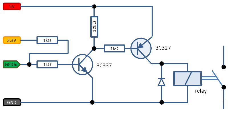
GPIO0 with relay
Relays need more current then a pin of the ESP8266 can deliver. Therefore, a transistor is often used for amplifying the signal.
When attaching a transistor to the IO pin you also have to face not pulling the level to low. Therefore a PNP transistor to high is a good solution. When the output current you need is higher than the amount the chip can deliver directly. If you don’t have a relays that is driven by 3.3 volts (very likely) you can use a second transistor to drive the relay using another voltage.
Here is a sample off driving a 5V relay:
GPIO 1 / Serial TX
You can control the blue LED if you do not need the TX function. TX is actually GPIO1 so by setting GPIO1 to HIGH will light up the LED of a ESP-01 board. Of course sending output to serial will spoil things.
GPIO2
This pin has to be high while booting or resetting the chip when you like to start the regular uploaded program. After starting the program you can use it for input and output like the GPIO0 pin.
Reset
The Reset(RST) line seems to be very sensitive regarding short spike impulses. There is an interesting investigation on this (in German) on the web site https://blog.thesen.eu/esp8266-reset-probleme-loesen-und-relais-stabil-schalten/.
The outcome from this: pull RST high with a resistor and add a 100nF capacitor.
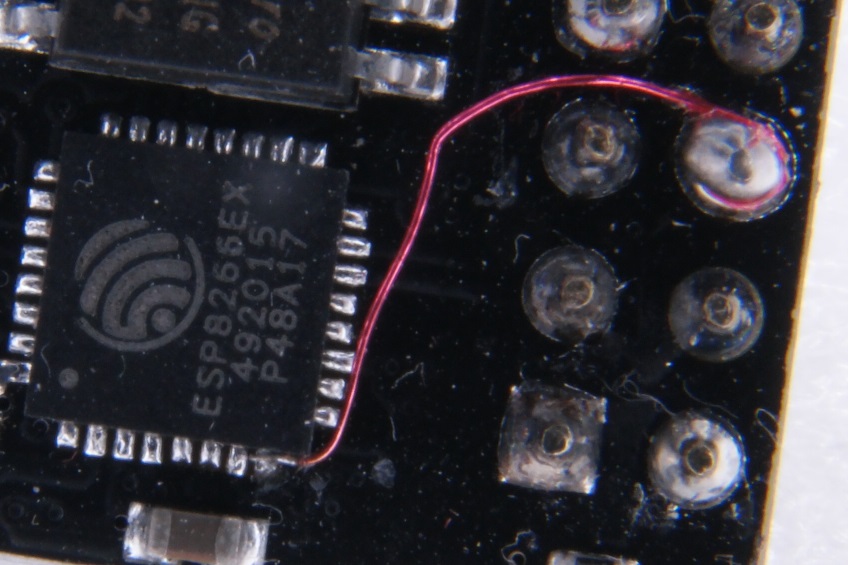
Modification for deep sleep mode
The ESP8266 supports a deep sleep mode that needs an external connection between the GPIO16 and the RESET.
Here is a picture on how to create such a connection on an ESP-01:
More details and hints on using the deep sleep mode can be found in deepsleep
Modification for supporting PUYA Flash chips
Some of the ESP8266 ESP-01 boards use a (cheaper) flash chip from the vendor PUYA. This chip has a slightly different behavior when writing data to the flash memory than the original flash chips that have been used. Therefore a modification in the code needs to be activated.
For version 2.5.2 of the ESP8266 board package this can be enabled by adding the following code to the Esp.h file in packages\esp8266\hardware\esp8266\2.5.2\cores\esp8266\Esp.h.
#ifndef PUYA_SUPPORT
  #define PUYA_SUPPORT 1
#endif
For the next version this option may be activated by default. See
https://github.com/esp8266/Arduino/pull/6362
Background information can be found in: https://github.com/esp8266/Arduino/issues/6221
See also
- https://www.instructables.com/id/How-to-use-the-ESP8266-01-pins/
- https://www.esp8266.com/viewtopic.php?t=11657
- https://www.instructables.com/id/USB-to-ESP-01-Board-Adapter-Modification/