ESP8266 NodeMCU development boards
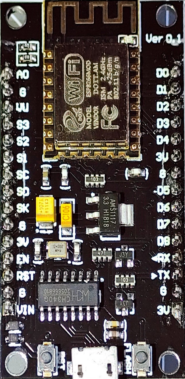
The NodeMCU boards are one of the most common development boards using ESP8266 modules. They offer an easy start into the ESP8266 development as they have all you need for programming, offer 4MByte flash memory and a LED on-board.
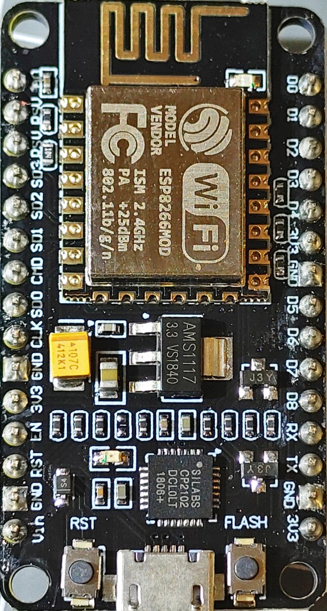
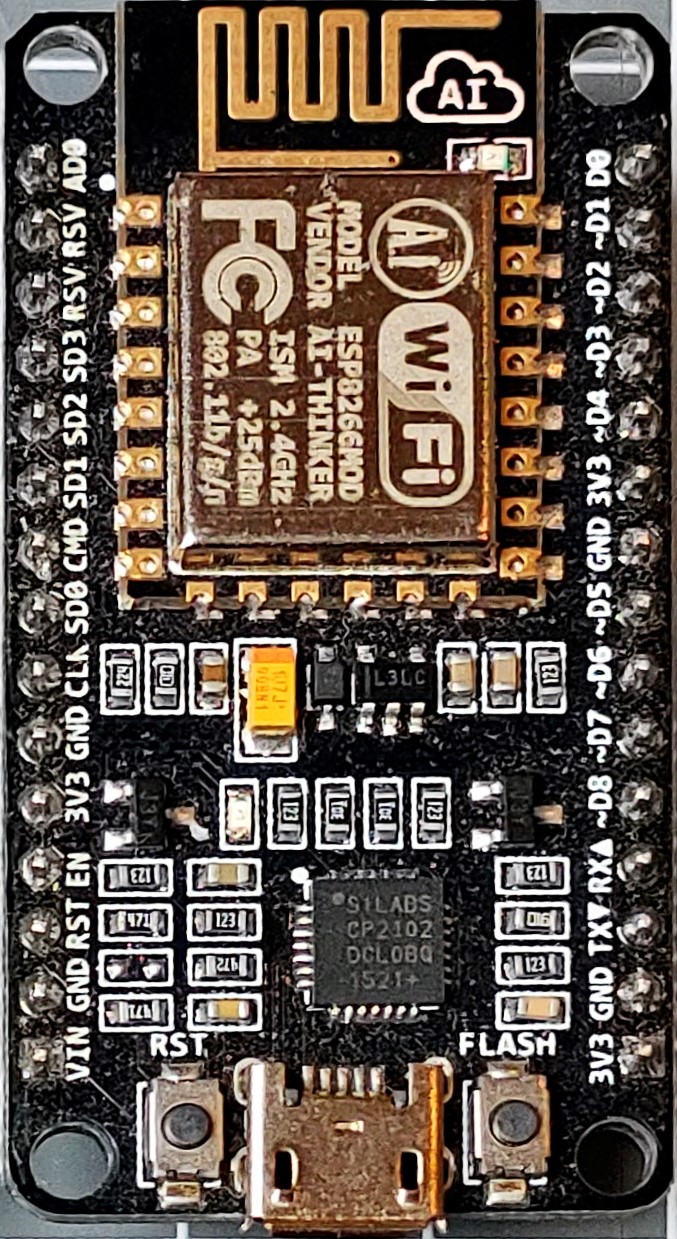
There are variants of this board available. I prefer and recommend those with a CP2102 USB-to-USART chip and with a DS1117 regulator that are slim enough to fit on a breadboard.
Features
- Based on ESP-12 or ESP-12E
- 4 Mbyte Flash ROM
- USB to serial adapter
- automatic programming mode
- breadboard friendly (most versions)
- 3.3 volts regulator
- On-board extra LED
NodeMCU is an open-source firmware for ESP8266 boards that enables scripting a IOT device using the Lua scripting language.
In general all these boards are exchangeable and can be used as replacements.
There are many derivate versions on the market but usually they follow the published design:
- The pin names Dnn are unified and correspond to GPIO pins with different numbers. Some older boards had different mappings. See also ESP8266 pins.
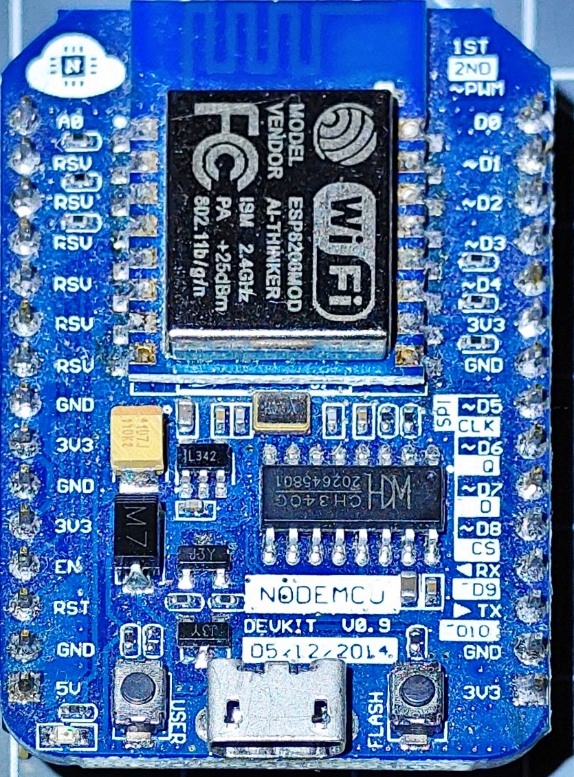
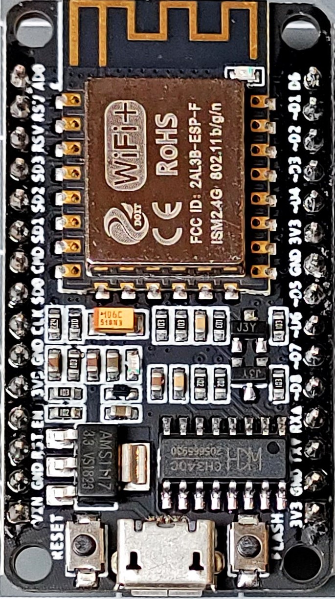
- There is a USB to Serial chip but version varies between CP2102 and CH340. If you upload sketches using more than 115200 baud or have problems finding USB adapter firmware this may be of interest.
- There is an onboard 3.3 V power regulator. When you have sensors or other peripherals that use the 3.3V from the board be sure you have a regulator that can drive the required current and that doesn’t get too hot.
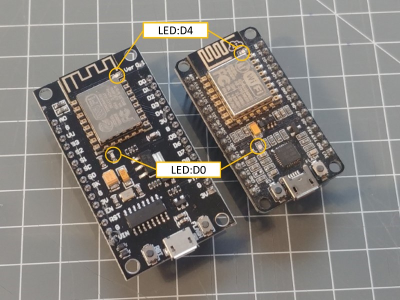
- There are multiple versions with different sizes. If you can choose take the smaller (right) one when used on a breadboard still offers space for using jumpers. The bigger (left) one leaves no place because it consumes the whole available breadboard width
Overview table
| GPIO | Pin | Functionality |
|---|---|---|
| GPIO0 | D3 | Flash Button |
| RESET | RESET Button | |
| GPIO2 | D4 | Blue LED on module |
| GPIO16 | D0 | LED on board |
Onboard Momentary Buttons
There are 2 Buttons on the Boards:
Reset – This button pulls the reset pin down to GND.
Flash – This button pulls the GPIO0(D3) pin down to GND. It can be used to manually start the program upload mode when is it pushed while resetting or powering up. Later it can be used for any input purpose as long it is leaving the pin in HIGH input when not used.
Onboard LEDs
There are two LEDs that can be used without any external components:
Vin / VUSB
There is a subtile difference in the nodeMCU bards from vendors regarding the availability and the usage of the 5V power supply.
Vin
- Some boards directly make the 5V power from the USB bus available on th Vin pin. This can then be used as a power output to drive 5V components like displays.
- Other boards us a diode to protect the board when this pin is really used as a power supply. Here the Vin pin cannot be used for output 5V power.
VU
- Some boards use the 2 reserved pins next to A0 to offer a dedicated pin attached to the 5V USB power supply and an additional GND pin. This can be used to power external chips and displays.
More to know
If you are most sure what characteristics a board has, try to find pictures and web sites that focus on describing the differences. Most of the boards behave the same.
There are boards that have a bigger PCB board that doesn’t work well with breadboards.
Burned boards
A overload of the 3.3 V output provided by the nodeMCU boards or a temporary shortcut between the GND and 3.3V pins can damage the onboard regulator or the board itself. It happened to me several times.
When only the regulator is damaged you can often cut off the one on the board and use still it by supplying 3.3 volts from an external power source.
After cutting the regulator the USB to serial chip may still work.
Some boards have a diode between the USB 5V line and the onboard regulator that is burned down and can be replaced.
Those boards may also be used by applying external power on +5V and +3.3V pins.
A multi purpose voltmeter is helpful.
System configuration
This env.json file can be used as a starting point for configuring this board type and includes all on-board hardware definitions:
{
  "device": {
    "main": {
      "name": "nodeding",
      "description": "nodeMCU board config",
      "reboottime": "24h",
      "button": "D3",
      "led": "D4",
      "I2C-SDA": "D2",
      "I2C-SCL": "D1"
    }
  },

  "ota": {
    "main": {
      "port": 8266,
      "passwd": "123",
      "description": "allow Over the Air Updates"
    }
  },

  "ntptime": {
    "0": {
        "ntpserver": "pool.ntp.org",
        "zone": "CET-1CEST,M3.5.0,M10.5.0/3"
    }
  },

  "ssdp": {
    "0": {
      "manufacturer": "nodemcu"
    }
  }
}
See also
- Boards overview
- NodeMCU Documentation
- Using the I2C bus
- https://frightanic.com/iot/comparison-of-esp8266-nodemcu-development-boards/
- https://www.nodemcu.com/index_en.html
- https://github.com/nodemcu/nodemcu-devkit-v1.0/blob/master/README.md
- ESP8266 board adoption for Arduino: https://arduino-esp8266.readthedocs.io/en/latest/index.html