Bulb Devices
Bulb devices using the ESP8266 chip are supported by the minimal sketch and can be controlled by the color and switch elements.
There are many different bulb devices that use RGB and white LED variants. The bulbs that use GPIOs with PWM or the chips like MY9231, MY9291.
The biggest challenge with these bulbs is that there is usually no easy way to get to the serial port without destroying the housing.
Therefore bulbs are used here, that can also be flashed with a new software via the network. This is done by the program tuya-convert that runs on a Raspberry pi.
The Minimal Example can be used in bulbs and other light devices.
Tuya Bulbs
The Manufacturer Tuya has created several WiFi Bulbs that are available from different sources. To check if a given bulb is using the ESP8266 processor the template registry for the TASMOTA firmware can be searched. Here you also find some information on the purpose of the GPIO pins and the used chips inside.
Flashing Tuya bulbs the first time using tuya-convert
It is easy to flash the minimal sketch using tuya-convert that can be used to flash firmware on brand new devices with the ESP8266 SoC chip as long as the firmware allows it. tuya-convert is using a weakness in the official firmware so when tuya updates the firmware there is the risk that this procedure will not work any more.
There is a good documentation and step-by-step instructions in https://tasmota.github.io/docs/Tuya-Convert/. The project is open-source available at https://github.com/ct-Open-Source/tuya-convert.
Place a Minimal.ino.bin file in the firmware folder on the raspberry pi to directly upload the minimal Homeding firmware.
Uploading a firmware using a USB-2-Serial converter
I cannot recommend his procedure because you probably will need to open the device by damaging some of the housing. I did it with a broken device.
Warning
- This warning is serious.
- Stay away from devices with contact to mains voltage.
- Never handle this module when connected to the mains voltage as the contacts are not safe.
- Uploading firmware to devices that have contact to mains voltage is dangerous.
- DO NOT connect the any device to the mains during flashing or while using the serial interface.
- You may kill your computer and yourself.
- When you are making these kind of projects you really need to know what you are doing.
- I have warned you, do not blame on me.
Other bulbs use different board layout and some investigation is required to find out. A good source of helping information is the repository of device specific templates for the TASMOTA firmware at https://templates.blakadder.com/bulb.html.
https://esphome.io/components/output/my9231.html
System Configuration for bulbs
In the env.json file the device specific settings must be configured.
In the settings on the device element the following properties are used:
name - the unique device name on the network.
homepage - The small size board implementation is a good candidate to be used as the standard UI.
connectTime - this value can be reduced to a shorter time as network configuration is not required for bulbs.
The OTA element enables updating the device firmware using the Arduino environment. A password should be specified.
{
  "device": {
    "0": {
      "loglevel": 0,
      "safemode": "false",
      "name": "bulb02",
      "description": "RGBW Bulb",
      "homepage": "/ding.htm",
      "connectTime": "2",
      "led": "D4"
    }
  },
  "ota": {
    "0": {
      "port": 8266,
      "passwd": "123",
      "description": "Listen for 'over the air' OTA Updates"
    }
  }
}
To have all control over the bulb LEDs a Switch Element and a Color Element can be used to control one of the Light Elements like Light Element, MY9291 Element or Neo Element.
Configuration bulb with MY9291 LED driver
There are bulb using a MY9291 chip to drive the LEDs using PWM output. The MY9291 Element can create the 4-channel signal using a data and a clock signal from the ESP8266 to the driver chip.
This Element behaves like a standard Light Element and supports WRGB color values, a general brightness and enable switch.
To configure such a element the data and clock pins need to be specified.
config.json
{
  "switch": {
    "en": {
      "title": "Mood-Light",
      "loglevel": "2",
      "description": "switch on/off",
      "onvalue": "my9291/l?enable=$v",
      "value": "0"
    }
  },
  "color": {
    "l": {
      "title": "Mood-Light",
      "loglevel": 2,
      "config": "WRGB",
      "mode": "fix",
      "duration": "2",
      "saturation": "255",
      "lightness": "127",
      "value": "x200000",
      "onValue": "my9291/l?value=$v"
    }
  },
  "my9291": {
    "l": {
      "title": "Mood-Light",
      "dataPin": "4",
      "clockPin": "5",
      "brightness": "255",
      "value": "x0000000F"
    }
  }
}
These bulbs are internally of this type:
- https://templates.blakadder.com/moko_YX-L01C-E27.html
- https://templates.blakadder.com/lyasi_pt-bw09.html
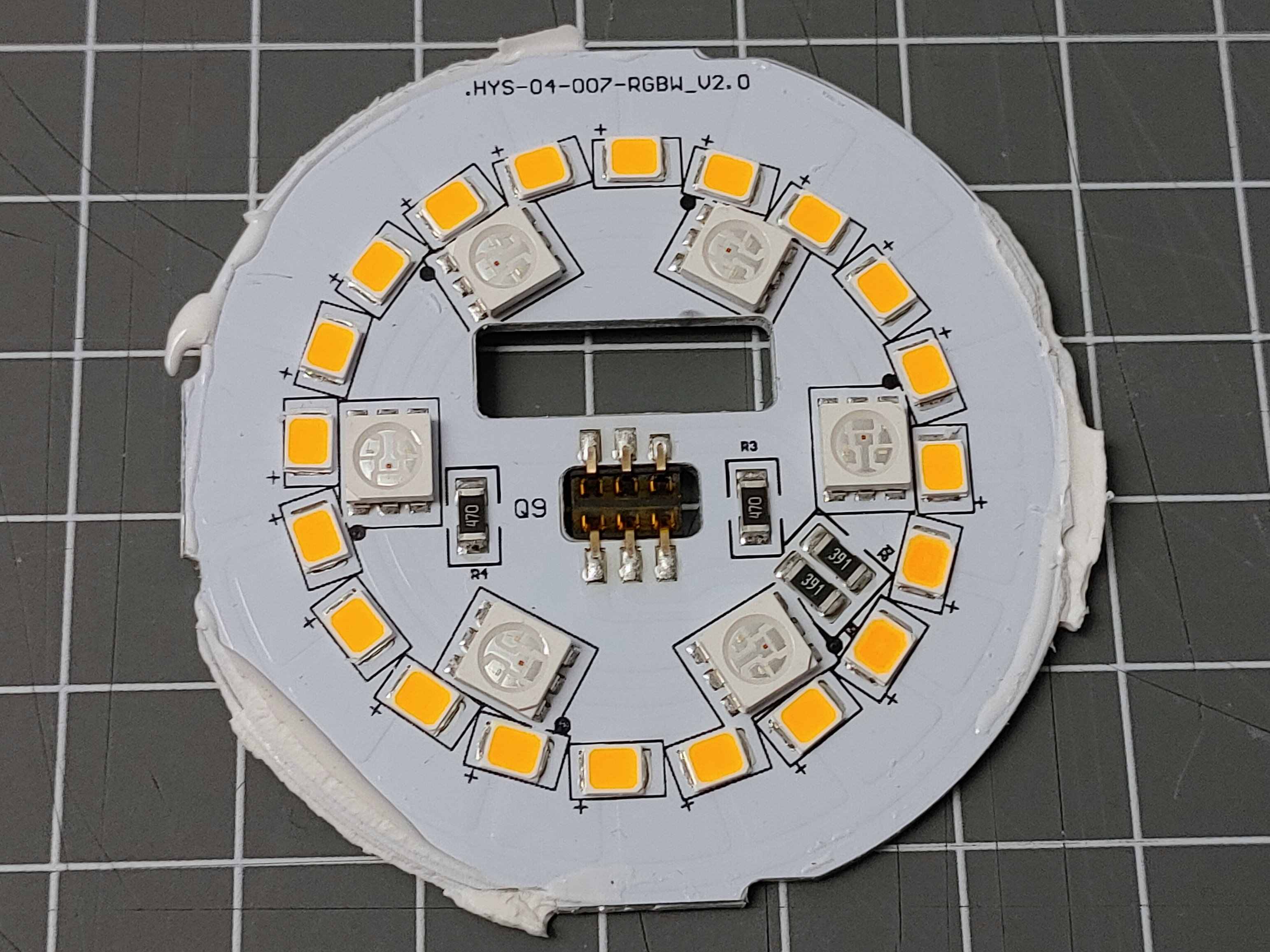
Here are some picture from a disassembly of a bulb:
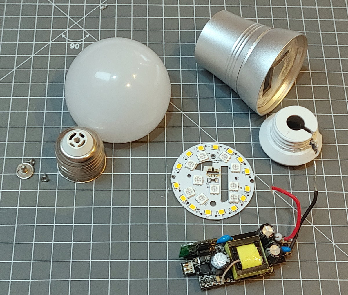
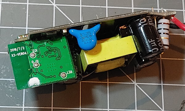
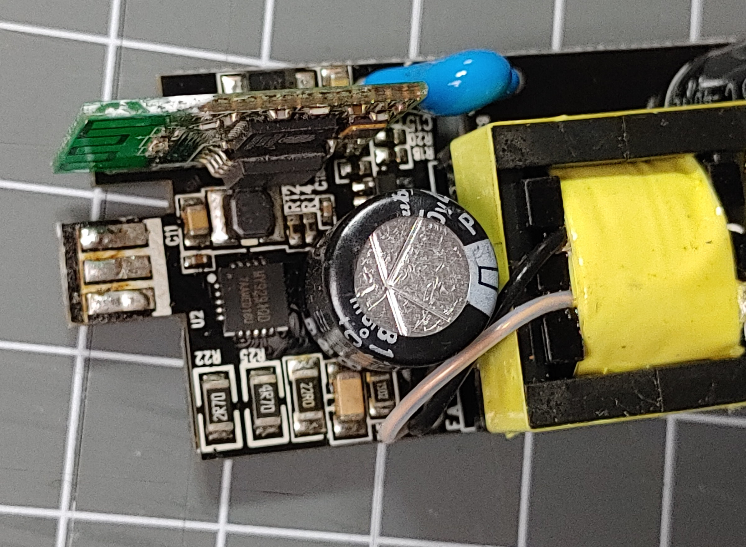
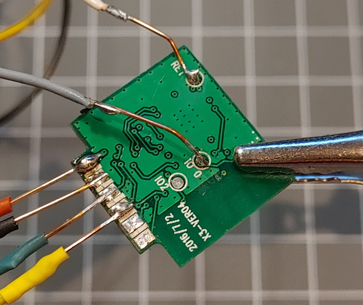
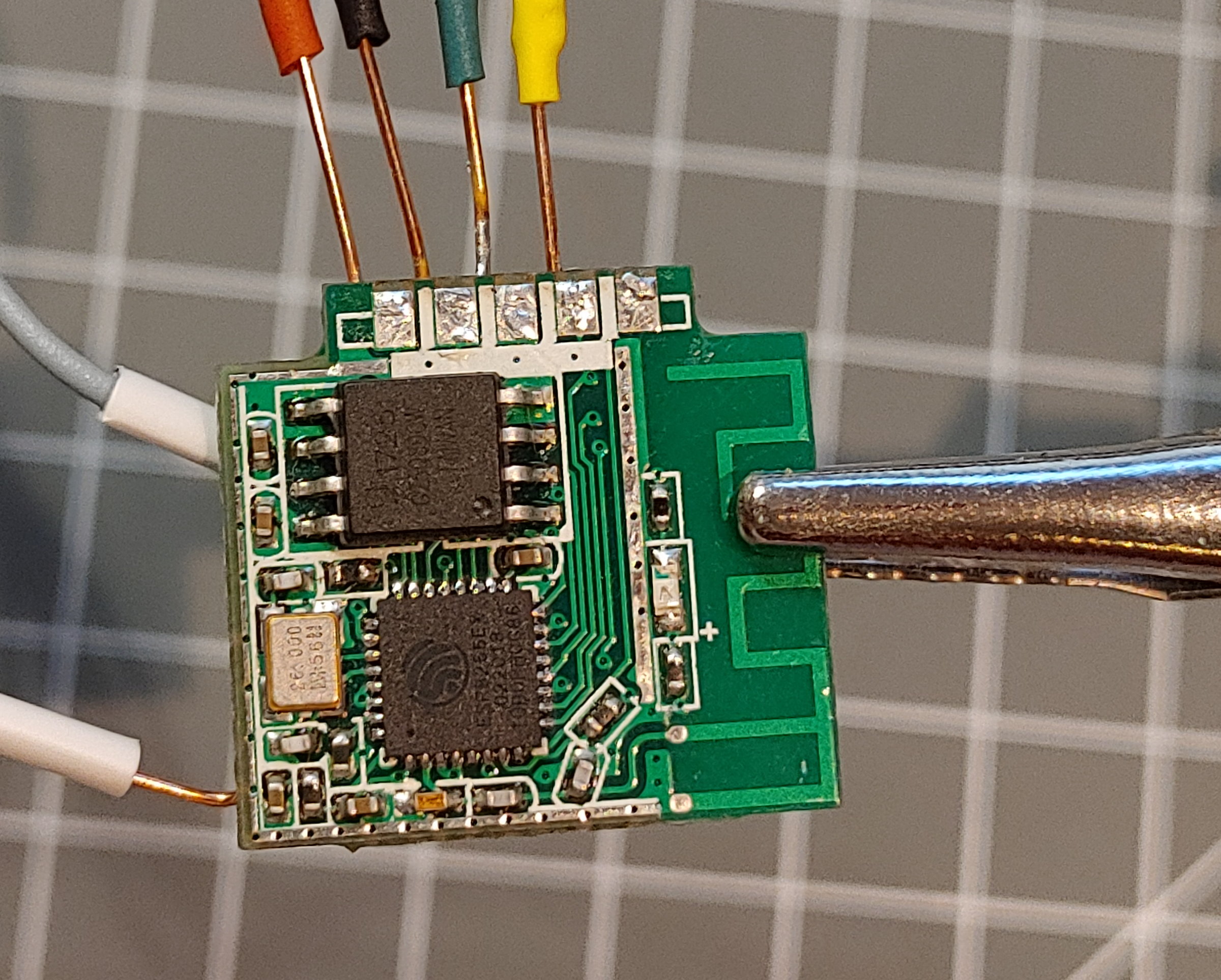
It is almost impossible to open this kind of a bulb and get access to the programming signals without breaking the housing.
I used a programming setup for ESP-01 boards with some wires that can be soldered easily to the connectors of the module with the ESP8266.
On the bottom side the signals VCC(3.3V), GND, RX and TX are available. The RESET and FLASH signals are available on 2 connectors on the bottom side.
Configuration bulb with PWM based LED driver
Many bulbs are using the PWM signals from the ESP8266 chip with some power switching mosfets to drive the LEDs. These can be controlled using the Light Element that can create 4-channels of PWM signals from a color value. It supports RGB and WRGB color values, a general brightness and enable switch.
config.json
{
  "switch": {
    "en": {
      "loglevel": "2",
      "description": "switch on/off",
      "onvalue": "light/l?enable=$v",
      "value": "0"
    }
  },
  "color": {
    "l": {
      "title": "color-bulb",
      "loglevel": 2,
      "config": "WRGB",
      "mode": "fix",
      "duration": "2",
      "saturation": "255",
      "lightness": "127",
      "value": "x203050",
      "onvalue": "light/l?value=$v"
    }
  },
  "light": {
    "l": {
      "title": "color-bulb",
      "loglevel": 0,
      "pin": "15,14,12,5",
      "value": "x200000"
    }
  }
}
These bulbs are internally of this type:
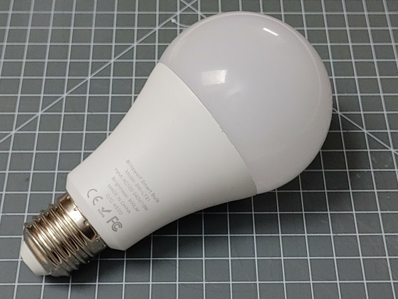
https://templates.blakadder.com/blitzwolf_BW-LT21.html
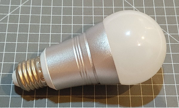
Here are some picture from a disassembly of a broken bulb:
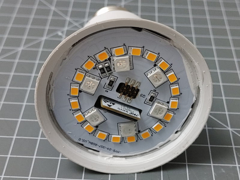
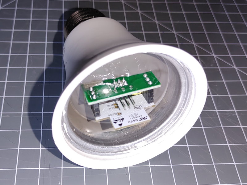
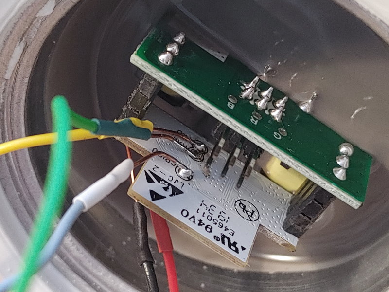
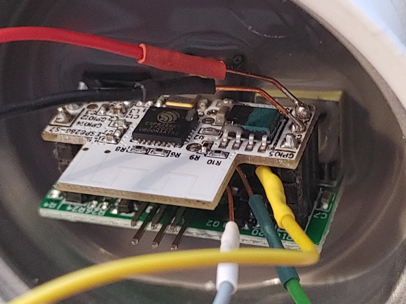
It is possible to open this bulb by gently pulling off the transparent cap. There are 2 small boards visible. The one with the processor has some good soldering pads for RX, TX and GPIO0. The VCC and GND signals are available on the connectors.
Soldering is a little bit tricky but can be managed.
I used a programming setup for ESP-01 boards with some wires that can be soldered easily to the connectors of the module with the ESP8266.
See also
- Color Element
- Switch Element
- Light Element
- MY9291 Element
- Neo Element
- https://www.heise.de/newsticker/meldung/Smart-Home-Hack-Tuya-veroeffentlicht-Sicherheitsupdate-4292028.html
- https://github.com/arendst/Sonoff-Tasmota/wiki/Tuya-OTA
- https://templates.blakadder.com/bulb.html.