White Adapter board for ESP8266
This ‘white’ adapter board helps soldering ESP-12 of similar boards in regular breadboards and prototype boards. The signals are straight forward routed from the board to the connectors with some exceptions only:
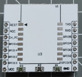
Resistor on the left
This 10 kOhm resistor connects the CH_PD to Module-VCC to pull CH_PD to HIGH by default. This is one of the required conditions so the module can start.
Some boards (at least some ESP-12E) already have an internal resistor for the same reason so the board just adds another one - not harmful.
Resistor in the middle
This 0 Ohm resistor actually is a bridge between VCC and Module-VCC required when no regulator is installed.
When you add a regulator (see below) this resistor MUST be removed.
Resistor on the right
This 10 kOhm resistor connects the GPIO15 to GND to pull GPIO15 to LOW by default.
This is one of the required conditions so the module can start.
Missing signals
The REST signal should be pulled up to HIGH by default but many boards also run without. If you like to have a RES button aside a 10 kOhm pull up Resistor should be added.
The GPIO0(D3) signal should be pulled up to HIGH for normal operation and to LOW for uploading a sketch using the Serial interface. I recommend to have a FLASH button and a 10 kOhm pull up resistor on this pin.
The GPIO0 signal should be pulled up to HIGH to start the board. Some boards (at least some ESP-12E) already have an internal resistor for the same reason but to add another one is not harmful.
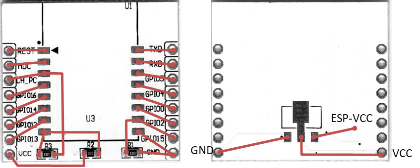
Adding a Regulator
To add a regulator to the bottom layer of the board the following steps must be done.
- Remove the Resistor/Bridge in the middle on the upper side.
- add a compatible regulator like MCP1703A or HT7333A with SOT-89 package. The signals must be like this:
          |IN|
     +-------------+
     |             |
     +-------------+
      |     |     |
     GND   IN    OUT
- add capacitors at least 100nF to the IN and OUT VCC level.