Witty-Board
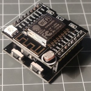
The Witty board offers a ESP8266-12F solution with a RGB LED, a LDR sensor and an input button. It can be used on a breadboard.
The Witty board is a cheap ESP8266 board that has a RGB LED, a LDR sensor and an input button. It can eb used on a breadboard.

2 Boards
The witty board uses 2 separate boards that are connected through some connectors. This allows using the board with or without the lower programming board.
For programming mode both boards need to be connected (the right way) and the USB cable must be connected to the lower board. After programming it is possible to used the upper board only by using the USB connector for power supply only.
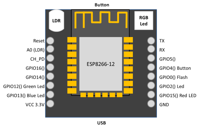
The upper board hosts a momentary switch at GPIO4(D2), the LED and a LDR sensor. The ESP8266-12F used offers 4 MB of flash memory.
The lower board hosts the CH340 USB to Serial bridge chip, the RST momentary switch and the GPIO0(D3) FLASH momentary switch.
Here are the signals on the connectors:
Witty vs. Adapter
The pins of the ESP-12 module are directly connected to the outer connectors (with exception VCC) in the same order very similar to the White Adapter board.
The USB adapter board (lower board) of the witty can be used for the Adapter boards but the need to have a regulator added. See White Adapter board.


The obvious difference are the added components and the existing voltage regulator so the board can be driven by 5 V from the lower board.
There is the option to add a voltage adapter to the White Adapter board as well.
System configuration
The device settings in env.json may look like this:
To enter the config mode the flash button GPIO0(D3) is configured here as usual. This button is located on the lower board. To use the button on the upper board GPIO4(D2) can be used also.
As the startup mode indicator the D7 is configured in this example using the blue of the RGB LED.
{
  "device": {
    "0": {
      "name": "witty",
      "title": "WittyBoard",
      "description": "Witty board with RGB LED and LDR",
      "loglevel": 2,
      "led": "D4",
      "button": "D3",
      "homepage": "/ding.htm"
    }
  },
  "ota": {
    "0": {
      "port": 8266,
      "passwd": "123",
      "description": "Listen for 'over the air' OTA Updates"
    }
  }
}
RGB LED
There is a RGB LED on the board that is directly driven by the following GPIO pins:
| Color | Pin |
|---|---|
| red | GPIO15(D8) |
| green | GPIO12(D6) |
| blue | GPIO13(D7) |
There is also a blue LED on the ESP-12 module on GPIO2(D4).
To reduce the power consumption the LEDs will not consuming the possible 20 mA per channel but the regulators reduce the current when maximum level is given by the GPIO pins. This allows using the RGB Led directly attached to the GPIO pins.
This is a good solution for using the LED as an indicator but not as a source of light.
It can be driven by the LightElement + ColorElement combination using the following configuration:
{
  "light": {
    "l": {
      "loglevel": 2,
      "pin": "D8,D6,D7",
      "mode": "pwm",
      "enable": "true",
      "value": "x603050",
      "brightness": "20"
    }
  },
  "color": {
    "l": {
      "title": "WittyRGB",
      "loglevel": 2,
      "config": "RGB",
      "mode": "fix",
      "duration": "4s",
      "value": "x200000",
      "onvalue": "light/l?value=$v",
      "onbrightness": "light/l?brightness=$v"
    }
  }
}
LDR
The willy board also has a Light Dependant Resistor (LDR) attached to the analog input The actual value can be read by using the AnalogInput Element.
By using an reference of about 300 it is possible to use it similar to a button. When covering the LDR sensor with a finger the values drops below.
"analog": {
  "0": {
    "reference" : 300,
    "onvalue": "device/0?log=analogvalue=$v",
    "onreference": "device/0?log=analogref=$v"
  }
}
The recipe LDR switch you can find a configuration that uses a LDR to create a touchless on/off switch.
Buttons
There is a button on the upper (main) board attached to the GPIO4(D2) pin that can be used for any purpose.
... ???
Taster: GPIO4(D2)
Example config.json
{
  "light": {
    "l": {
      "pin": "D8,D6,D7",
      "value": "x203050"
    }
  },
  "analog": {
    "0": {
      "reference": 300,
      "onvalue": "device/0?log=analogvalue=$v",
      "onreference": "device/0?log=analogref=$v"
    }
  }
}
See also
- https://blog.moneybag.de/fhem-witty-board-einfache-iot-funktionen-schnell-gebaut/
- https://www.faranux.com/product/witty-cloud-board/
- https://www.schatenseite.de/2016/04/22/esp8266-witty-cloud-modul/