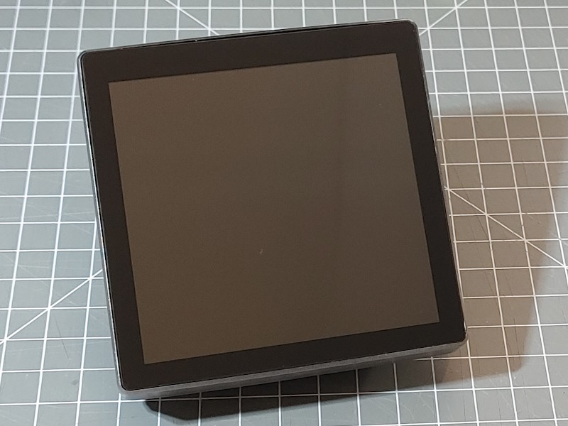
Panel ESP32-4848S040
This panel is a ready to used wall-mount device based on the ESP32-S3 processor supporting 16M Flash and 8M PSRAM Memory in combination with a 480px * 480px 16 bit color display and touch controller.
This panel including advanced graphic features is supported by the HomeDing Display Example.
This board is equipped with:
- ESP32-S3 processor
- 16 MByte Flash in QIO mode
- 8 MByte PSRAM OPI
- 4.3 inch, 480 * 480 px Display based on ST7701: 16 bit color, special ESP32-S3 parallel mode The display is supported by the “GFX Library for Arduino”.
- Touch Sensor: GT911 on I2C, Address 0x5D
- I2C bus using SDA=19, CLK=20
- SD Card slot
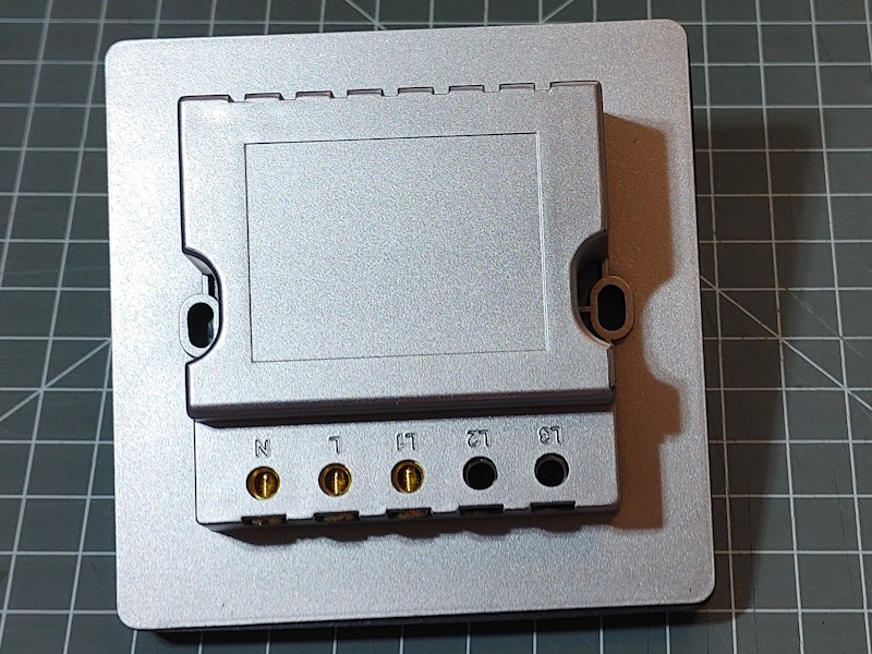
There are 2 versions available equipped with 1 to 3 relays.
A download of supporting files is available at
http://pan.jczn1688.com/pd/1/ESP32 module/4.0inch_ESP32-4848S040.zip
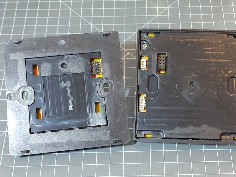
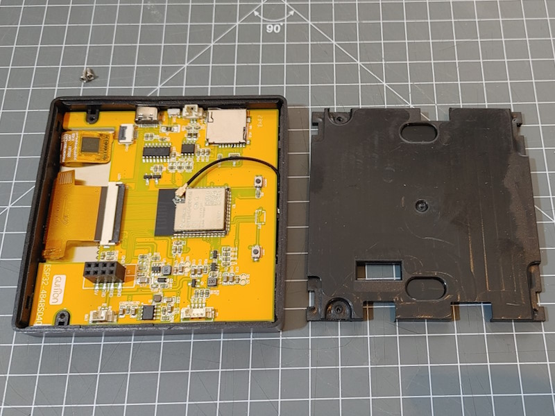
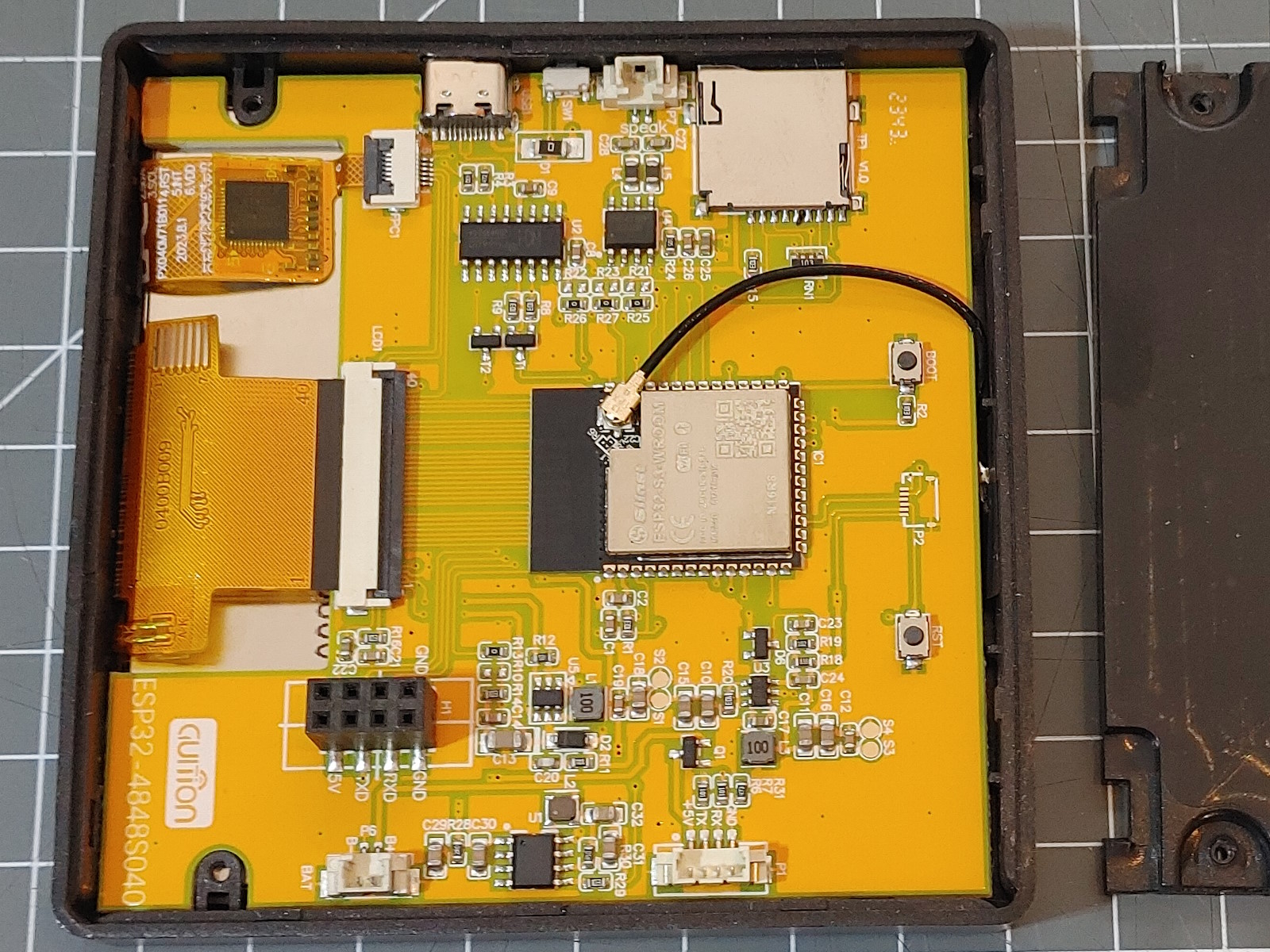
The front part contains the ESP32-S3 processor module and most of the built-in features. There are extra connectors for connecting a LIPO battery, a speaker and the serial interface that cannot be used when the panel is closed.
The back part contains a power supply and the 1 to 3 relays.
Both parts are connected by the 8-pin connector.
Warning
- This warning is serious.
- Stay away from devices with contact to mains voltage.
- Never handle this module when connected to the mains voltage as the contacts are not safe.
- Uploading firmware to devices that have contact to mains voltage is dangerous.
- DO NOT connect the any device to the mains during flashing or while using the serial interface.
- You may kill your computer and yourself.
- When you are making these kind of projects you really need to know what you are doing.
- I have warned you, do not blame on me.
Arduino Configuration
The ESP32S3 Dev Module (esp32) can be used with the following settings:
- JTAG Adapter: Disbled
- PSRAM: OPI PSRAM
- Flash Mode: QIO 80MHz
- Flash Size: 16MByte (128Mbit)
- Arduino Runs On: Core 1
- Events Runs On: Core 1
- USB Mode: Hardware CDC amd JTAG
- USB CDC On Boot: Disabled
- USB Firmware MSC on Boot: Disabled
- Upload Mode: UAT0 / Hardware CDC
- Partition Scheme: ___
- CPU Frequency: 240MHz (WiFi)
- Upload Speed: 921600
- Core Debug Level: None
- Erase All Flash: Disabled
The USB-C connector uses a CH340 USB to Serial converter chip and connects to the Serial port of the ESP32-S3.
env.json Configuration
This is a board configuration in the env.json file to support the hardware configuration of this board:
{
  "device": {
    "0": {
      "name": "wallpanel",
      "title": "ESP32-4848S040",
      "description": "480*480 Touch Panel from JCZN",
      "loglevel": "2",
      "button": "0",
      "logfile": 1,
      "safemode": "false",
      "homepage": "/board.htm",
      "cache": "max-age=600",
      "i2c-SDA": "19",
      "i2c-SCL": "45",
      "spi-scl": 48,
      "spi-mosi": 47,
      "spi-miso": 41
    }
  },

  "ota": { "0": {} },

  "ntptime": {
    "0": {
      "zone": "CET-1CEST,M3.5.0,M10.5.0/3"
    }
  },

  "DisplayEsp32panel": {
    "0": {
      "width": "480",
      "height": "480",
      "rotation": "0",
      "lightpin": 38,

      "cspin": 39,
      "spiclk": 48,
      "spimosi": 47,
      "buspins": "11,12,13,14,0, 8,20,3,46,9,10, 4,5,6,7,15",

      "color": "x000000",
      "background": "#cccccc",
      "border": "black"
    }
  },

  "DisplayTouchGT911": {
    "0": {
      "address": "0x5D"
    }
  },

  "sd": {
    "0": {
      "cspin": "42"
    }
  },

  "digitalout": {
    "relay1": {
      "loglevel": "2",
      "title": "Relay 1",
      "pin": "40"
    }
  }
}
I2C bus
The display touch controller is connected using the i2c bus. The ESP32 pins in used are specified in the device configuration.
SPI bus
The display and the SD card are using the SPI bus. The ESP32 pins in used are specified in the device configuration.
Display
The IPS LCD display is supporting a resolution of 480 * 480 pixels and 16-bit colors and is based on the ST7701 chip.
It is connected to the processor using the ESP32-S3 specific 16-bit data bus using DMA to transfer for pixel data and the SPI bus in 9-bit mode for commands and configuration.
The SPI bus is using the 9-bit data transfer can only be used for sending information. As the 9-bit mode is not supported by the Arduino environment the spi bus configuration must be given on the display element.
The pins in use can be found in the env.json configuration.
It is supported by current version of the “GFX Library for Arduino”.
Both communication mechanisms (9-bit SPI and 16-bit Panel) must be configured and the display must be initialized with the board specific initialization sequence from the provided examples.
// 9-bit mode SPI
bus = new Arduino_ESP32SPI(
    GFX_NOT_DEFINED /* DC */, 39 /* CS */, 48 /* SCK */, 47 /* MOSI */, GFX_NOT_DEFINED /* MISO */);

// panel (Hardware) specific
Arduino_ESP32RGBPanel *rgbpanel = new Arduino_ESP32RGBPanel(
    18 /* DE */, 17 /* VSYNC */, 16 /* HSYNC */, 21 /* PCLK */,
    4 /* R0 */, 5 /* R1 */, 6 /* R2 */, 7 /* R3 */, 15 /* R4 */,
    8 /* G0 */, 20 /* G1 */, 3 /* G2 */, 46 /* G3 */, 9 /* G4 */, 10 /* G5 */,
    11 /* B0 */, 12 /* B1 */, 13 /* B2 */, 14 /* B3 */, 0 /* B4 */,
    1 /* hsync_polarity */, 10 /* hsync_front_porch */, 8 /* hsync_pulse_width */, 50 /* hsync_back_porch */,
    1 /* vsync_polarity */, 10 /* vsync_front_porch */, 8 /* vsync_pulse_width */, 20 /* vsync_back_porch */);

// panel parameters & setup
gfx = new Arduino_RGB_Display(
    480 /* width */, 480 /* height */, rgbpanel, 0 /* rotation */, true /* auto_flush */,
    bus, GFX_NOT_DEFINED /* RST */, st7701_4848S040_init, sizeof(st7701_4848S040_init));
The init sequence can be found in the examples for this board or in the HomeDing Display implementation: <>
Touch Controller
This devices uses a GT911 display touch chip connected to he I2C bus. The Display TouchGT911 Element can be used with address 0x5D.
The reset and interrupt pins are not connected.
Relay control
The 1 to 3 relays in the device are located in the back part of the module and can be controlled using the GPIO 40, 2 and 1. The env.json configuration above has a Digital Output Element for the relay # 1.
Battery Connector
I have not yet found out how this can be used.
maybe: IP5306
Speaker Connector
I have not yet found out how this can be used. maybe: NS4168
SW1
There is a hidden momentary button beside the USB Connector.
I have not yet found out how this is connected.
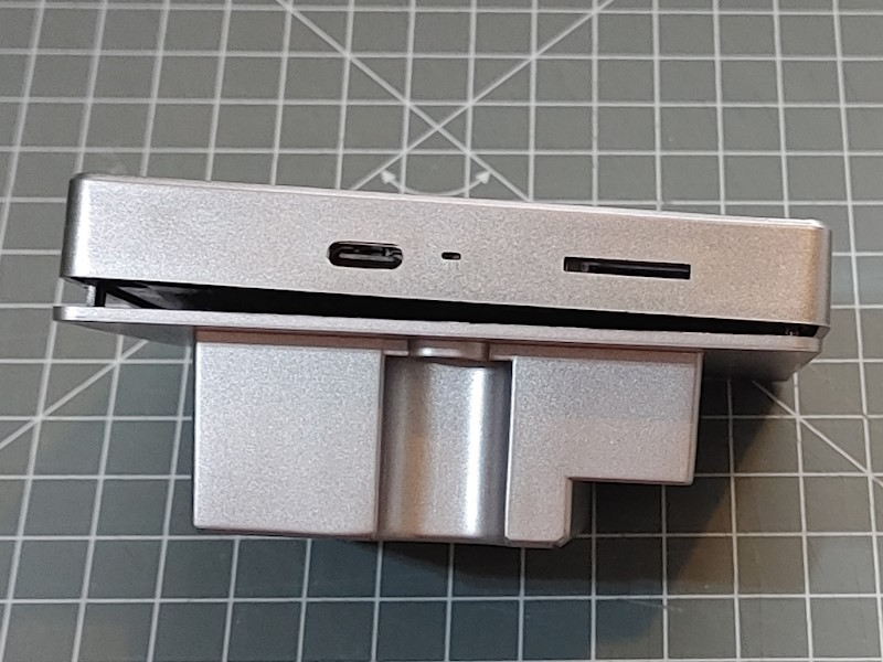
USB-C Connector
This can be used for uploading new software and powering the device. There is a CH350 USB-to-Serial chip used for flashing the software so no direct connection using the internal USB of the ESP32-S3.
TF Card
The module has a SD card connector and SD cards can be inserted in the slot above the USB connector.
This enables using files on the sd card by configuring the SD Element for several use-cases. The specific configuration can be found above.
The Micro SD Card supports the SPI Mode using the following GPIOs:
| SD Pin | Description | ESP32 Pin |
|---|---|---|
| 1 | not used | |
| 2 | Chip Select (CS) | GPIO42 |
| 3 | SPI-MOSI (Data in) | GPIO47 |
| 4 | VDD | |
| 5 | SPI-CLK | GPIO48 |
| 6 | GND | |
| 7 | SPI-MISO (Data out) | GPIO41 |
| 8 | not used |
See also
- ESP32-S3 Boards
- http://www.jczn1688.com
- http://pan.jczn1688.com/pd/1/ESP32 module/4.0inch_ESP32-4848S040.zip
- https://eshop.eca.ir/برد-تغذیه-سوئیچینگ/22071-ماژول-تغذیه-سوئیچینگ-12-ولت-جریان-ثابت-450ma-نسل-6.html