Digital Output Element
The DigitalOutElement is used with the GPIO pins of the board to create a digital output level based on actions sent to the element. This can e.g. be used to switch a LED or relay on/off.
Web UI for the Timer Element
There is a dedicated card for this element available that will be used on the web server config and landing pages:
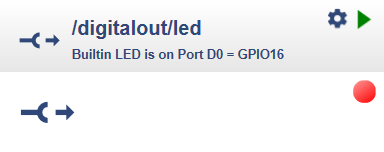
The boolean value indicator is showing the actual output level using red(0) and green(1) color.
Element Configuration
The following properties are available for configuration of the element.
pin* – Specifies the hardware number of the pin.
invert – set to ‘true’ for invert mode. Normal mode is default.
value – The initial value of the output.
From the base element implementation the following properties are available for configuration:
title – Caption text for the element. Used by the element specific cards on the dash boards.
description – A line of text that gives a short description of the device used in the web UI.
room – The location of the device.
loglevel – This property holds the element specific log level. The default value is LOGGER_LEVEL_ERR == 1.
startup – This property can be used to start the element using a different initialization phase. Possible values are “sys”, “net”, “time”. See The Startup sequence.
* This parameter must be specified.
The physical output level can differ from the logical output value because some external components require am active HIGH and other active LOW signal.
This can be configured by using the invert property.
In normal mode (invert: “false”) a HIGH output level is created on value 1.
In invert mode (invert: “true”) a LOW output level is created on value 1. Normal mode is default.
There are some GPIO pins it the ESP8266 and ESP32 that require to be HIGH when booting. Here the invert mode is recommended for the output signal.
Element Actions
The following actions are available to change the output level:
| Action | Description |
|---|---|
on |
sets the logical output to value 1. |
off |
sets the logical output to value 0. |
value |
The new logical value of the output. |
The physical output depends on invert.
Configuration Example
This example shows how to configure this element:
{
  "digitalout": {
    "led": {
      "pin": "D0",
      "invert": "true",
      "value": "0",
      "description": "Builtin LED is on Port D0 = GPIO16"
    }
  }
}
State
The state of the digitalout element includes:
active - Is set to true when the element is active.
value - Current output value of the element.
Example State
{
  "digitalout/led": {
    "active":"false",
    "value":"0"
  }
}