Outdoor Sensor
Some weather parameters are interesting to be measured by using an outside sensor like
- Temperature
- Humidity
- Sun light
- Rain
This is how to build a device that simply captures the air temperature and humidity parameters from a DHT22 sensor by using the low-code Homeding library. There are many sensor elements supported by the library so it is easy to used a different sensor or add other sensors as this is just done by configuration.
This project is a good starter project as well to explore the possibilities for building sensors gadgets yourself.
In the Outdoor Sensor with Solar Panel project the additional components and configuration changes are explained to run a sensor with low-power consumption with a solar panel.
In the Weather forecast display a device with a display is explained that can visualize sensor values and also forecast information from an internet based data source.
Build for the outside
In contrast to the sensor that must be exposed to the outside air the microprocessor board should be placed into a water proof housing. Only the USB power line and the sensor wires are going out.
This sensor is placed in a location where direct rain and sunlight could not reach it so there was no need for special shielding. Also USB power is available and the device can be powered all the time.


To inspect the current values the devices is connected to the local WiFi and has a built-in web server, also provided by the Homeding library that shows both values of the sensor on a tile.
Just open the Board page to see the HTML UI of the element:

This project shows the basic of building an outdoor sensor. There are possible extensions that can be added by configuration:
- a Log Element that can capture the values and display as a line chart.
- using a solar panel and LiPo batteries and run the sensor on low power mode.
Supplies
This is all you need to build this project
- A ESP8266 based board like the nodemcu board
- A DHT22 or compatible sensor to measure temperature and humidity.
- A USB plug and a micro-usb cable for power supply.
- A water proof housing
- Wires, solder, …
Prepare Arduino Environment for ESP8266
To build the software you need a working Arduino environment for ESP8266:
-
Install latest version of Arduino IDE (currently version 1.8.13).
-
Use Board Manager to install the install the esp8266 support.
A detailed instruction can be found here: https://arduino-esp8266.readthedocs.io/en/latest/installing.html#boards-manager
-
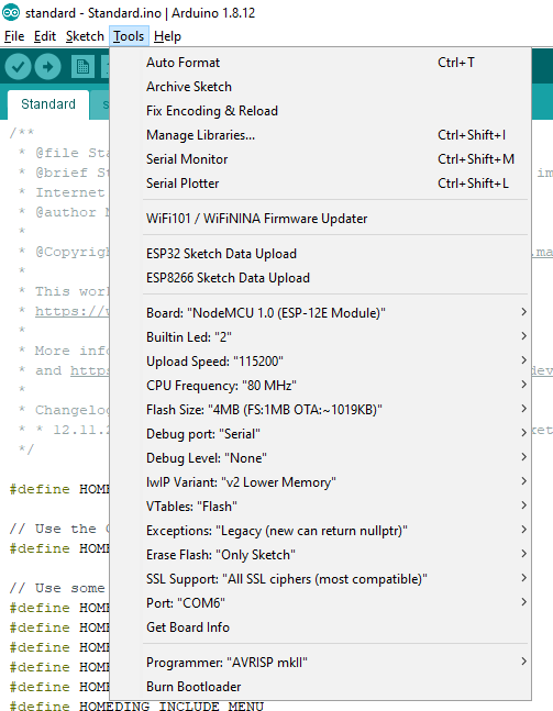
Setup the board options for a NodeMCU 1.0 with 1MByte SPIFFS File System

Include required libraries
To install the HomeDing library use the Arduino Library Manager and search for HomeDing.
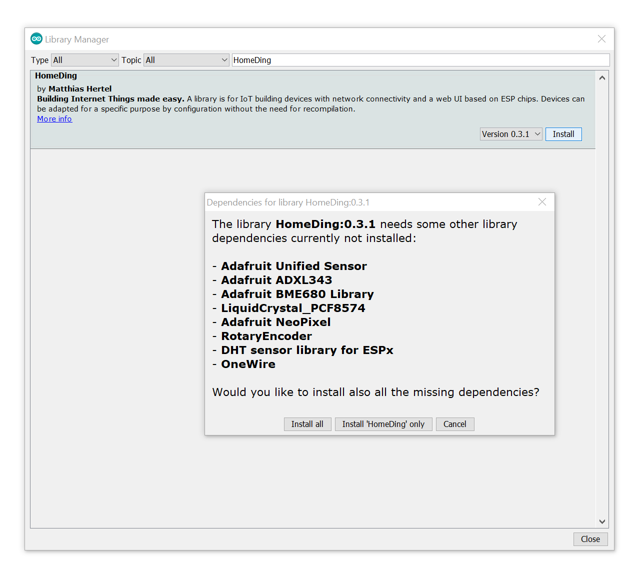
When you install the HomeDing library you will see a popup with some required libraries that can be installed automatically as the HomeDing library relies on some common extra libraries for sensors and displays to work.

Sometimes (with unknown reasons) the installation of the libraries fails so all the required libraries need to be installed manually.
More details about the required libraries can be found on the documentation website at https://homeding.github.io/elements/index.htm.
Upload the standard example sketch
The Standard Example already includes all that is needed so simply use this example. Some configuration will be required, see below.
As you can see on the picture above also a ESP-01 board can be used that only has 1MByte of Flash memory. The the Minimal Example is a better project to start with.
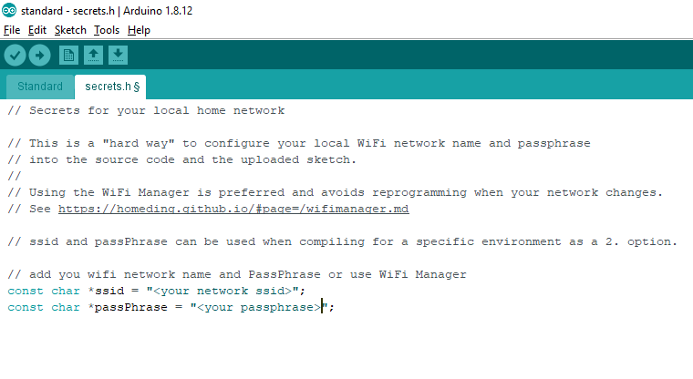
For simplicity on adding the new device to the network you may add the SSID and passphrase of your home WiFi in the secrets.h
file next to the standard.ino sketch file.
But you can also use the built-in WiFi Manager to add the device to the network without this hard-coded configuration.

Now everything regarding implementation of the sketch is done and the firmware can be compiled and uploaded.
When the device boots with the new firmware for the first time you can use the Serial Monitor to inspect the output during booting.
Here you can see the information about the interim name of the device, the IP address and the network it connected to:
00:00:10 sys:i ESP-5D2122 192.168.2.175
00:00:10 sys:i Connected to DEVNET unsafe
Here the temporary devicename is ESP-5D2122 and DEVNET is the network joined.
Joining the WiFi Network using the WiFi Manager
When you have configured your local WiFi network in secrets.h the device will be available on your network.
When you do not want to hard-code your network passphrase use the built-in WiFi Manager to join the network you can reach the configuration page
by joining the temporary device hotspot named homeding-xxxxxx and opening
http://192.168.4.1/$setup.
A more detailed description on this process can be found on the page Step by Step Bring your device to work.
Upload the web UI
This steps enables the Web UI of the device by uploading the required files into the filesystem. This method is very useful when starting with a new board.
The simplest way to do this is by using the Builtin Web based Upload Utility that can be reached at http://ESP-xxxxxx/$update.htm.

By pressing the start button all required files from the homeding documentation website are transferred to the device.
The files are also available at https://github.com/HomeDing/homeding.github.io/tree/master/v02 it you like to know what will be uploaded.
After the upload has finished you can navigate to the next step to select an icon for the device. Take DHT and press “start” to place some icon files on the device.
When navigating to the next step the embedded IDE will be started.
Configuration Files
2 configuration files must be used to configure the sensor. To do this we can used the built-in micro IDE to create these 2 files.
The embedded IDE can be opened from the homepage using the IDE menu item.
env.json
The env.json contains only the system settings that do not change while configuring a specific functionality.
To create a env.json file on the device just open the IDE from the menu
and copy the following configuration into the right text area and then click the save button.
When requested enter /env.json into the filename field.
When you reboot the device either by pressing the reset button on the board or in the UI the device will register itself
on the network using the name specified in the env.json file (here: outdoor).
Opening the url http://outdoor will redirect directly to the built-in dashboard.
{
  "device": {
    "0": {
      "name": "outdoor",
      "reboottime": "24h",
      "description": "Outdoor sensor",
      "logfile": 1,
      "safemode": "false",
      "homepage":"/board.htm",
      "led": "D0",
      "button": "D4"
    }
  },
  "ota": {
    "0": {
      "port": 8266,
      "passwd": "123",
      "description": "Listen for 'over the air' OTA Updates"
    }
  },
  "ssdp": {
    "0": {
      "ModelUrl": "https://www.mathertel.de/Arduino"
    }
  }
}
config.json
The config.json contains the sensor specific settings.
To create a config.json file on the device just open the IDE from the menu
and copy the following configuration into the right text area and then click the save button.
When requested enter /config.json into the filename field.
{
  "dht": {
    "on": {
      "type": "DHT22",
      "description": "Temperature and Humidity sensor",
      "pin": "D5",
      "readtime": "30s",
      "resendtime": "2m"
    }
  }
}
Wiring (simple)
The principle wiring of a DHT22 sensor can be seen in this picture:

As you can see in the config.json file the data pin that was configured on the software side is the D5 GPIO pin so data from the sensor chip must be connected here.
| ESP board | Sensor | Signal |
|---|---|---|
| GND | GND | GND signal |
| 3.3 | VCC | 3.3 V Power |
| D5 | Data | Data line using the DHT22 protocol |
The resistor in the diagram must not be present as hardware because there is a configuration on GPIOs to enable a integrated pull up resistor.
More details on the DHT22 connecting options can be found in the DHT Element description and in More Robust Sensor wiring below.
Restart
Now restart the device by using the reset button on the board, in the IDE or just detach and attach the USB cable and the device.
Now the LED will blink several times while connecting to the network.
Extending a humidity log
This configuration will add a log file with the humidity from the sensor saving a value every 30 seconds.
The dht element gets the additional configuration to send the current value to the log element using an action:
"onhumidity": "log/hum?value=$v"Actions are the way the elements inside a device can communicate and the source element is sending actions most of the time to all consumers. Actions can also be sent across the network to other devices.
An accurate time is required for logging. Therefore we use the ntptime element to get the current time from a ntp server with adjustments to the timezone you are living in.
"ntptime": {
  "0": {
    "zone": "CET-1CEST,M3.5.0,M10.5.0/3"
  }
},
You may want to adjust the time zone to fit your location in the ntptime element. This element is often configured in the env.json file but also works in the config.json file.
The Log Element is configured to collect data into a pair of files:
"log": {
  "h": {
    "description": "log humidity",
    "averagetime": "00:10:00",
    "filesize": "10000",
    "filename": "/humlog.txt"
  }
}
The same can be done for temperature.
Now the config.json file should contain:
{
  "dht": {
    "on": {
      "type": "DHT22",
      "description": "Temperature and Humidity sensor",
      "pin": "D5",
      "readtime": "30s",
      "onhumidity": "log/h?value=$v",
      "ontemperature": "log/t?value=$v"
    }
  },
  "ntptime": {
    "0": {
      "zone": "CET-1CEST,M3.5.0,M10.5.0/3"
    }
  },
  "log": {
    "t": {
      "description": "log temperature",
      "averagetime": "00:10:00",
      "filesize": "10000",
      "filename": "/templog.txt"
    },
    "h": {
      "description": "log humidity",
      "averagetime": "00:10:00",
      "filesize": "10000",
      "filename": "/humlog.txt"
    }
  }
}
Click “save” and reboot the device again so the elements will start working.
Extending a temperature log
very similar to the step before a temperature log can be added. The final config.json contains also the log/t configuration.
More Robust Sensor wiring
The DHT22 sensor sometimes stops working. This happens more often when 3.3V is used as a power supply and occurs sometimes after many days of operation.
As a corrective measure it is possible to use the sensor reset mechanism if the DHT Element to enable power some seconds before a sensor reading is required and then cut off power after getting a value.
The DHT22 wiring has to be changed so that the GND pin is attached to a GPIO (D6 is used here).
In the config.json file the 3 parameters have to be added:
{
  "dht": {
    "on": {
      ...
      "restart": "true",
      "powerpin": "D6",
      "powerinvert": "true",
      ...
    }
  }
}
Device Dashboard
The information the device is gathering can be found on the device dashboard.
Open http://outdoor/board.htm to open the dashboard and see current sensor values.

Further Options
The HomeDing library offers a lot of options that can be used to create more value from your sensor device.
- You can setup a new device with a display and then configure the sensor to send over the actual values using remote actions.
- The same sensor type can be used in-house also to log temperature and humidity, just build another one.
- You can add more sensor values like air pressure and see high and low weather effects and trends.
See the story Build a In-house IoT Air Quality sensor - You can configure some low energy options and run your sensor by solar power.
See the story Build a In-house IoT Air Quality sensor
See also
- DHT Element
- Dallas Element temperature
- BMP280 Element temperature and air pressure
- BME680 Element temperature, humidity, air pressure and air resistance.
- Story - Outdoor Sensor with Solar Panel
- Story - Outdoor Sensor