DHT Element
The DHT Element allows retrieving temperature and humidity values from the DHT11, DHT22 and AM2302 sensors and creates actions when new values are available.
The current values are also sent out to other elements using actions when they stay the same for some time to allow remote devices to resume to the current values after reboot or network outages.
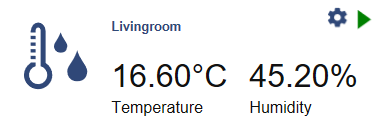
Web UI for the DHT Element
There is a dedicated card for this element available that shows the actual temperature and humidity.
Using the DHT Element
The DHT Element is not part of the core set of elements because the low level communication to the chips the DHTNEW library is used and needs to be installed using the Arduino library manager.
Install the DHTNEW library by Rob Tillaart before including this element. When you install the HomeDing Library by using the Arduino library manager it can be installed as a dependency.
The HOMEDING_INCLUDE_DHT must be defined in the main sketch to compile and register the element.
// Use some more Elements that need additional libraries
#define HOMEDING_INCLUDE_DHT
#include <HomeDing.h>
The following sensor chips from the DHT family are supported by the DHTesp library:
- DHT11
- DHT22 (identical to AM2302)
- AM2302
- AM2320 (in dht mode)
- RHT03
more details can be found at https://github.com/beegee-tokyo/DHTesp
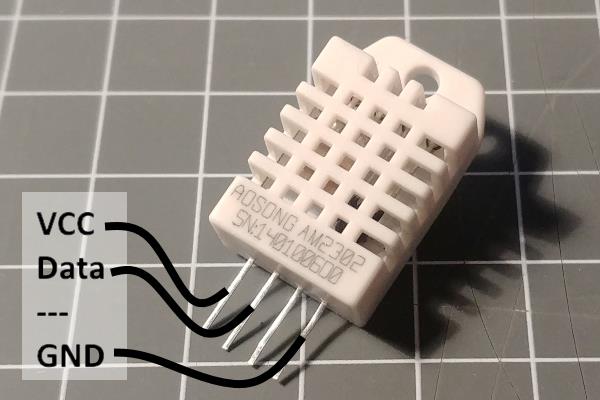
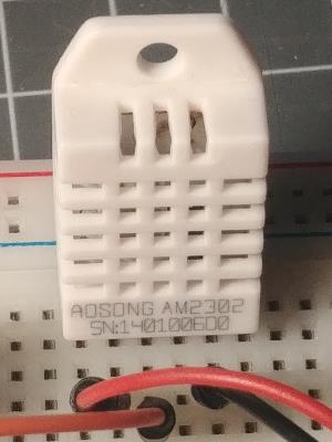
Connecting a DHT Sensor
The sample configuration coming with the DHT22 recipes is configured to use a DHT22 type of sensor with the data line attached to a GPIO like (D5).
The configuration of the used pin can be changed easily by modifying the element properties in the config.json file.
Connecting a AM2320 Sensor
The AM2320 sensor is a drop-in replacement for the DHT22 with almost the same wiring and smaller in size.
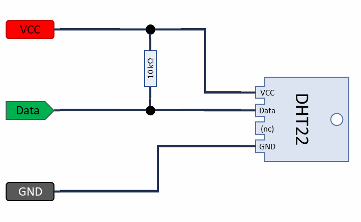
In addition to the DHT22 wiring the not connected (nc) pin needs also to be connected to GND to use the compatible data protocol.
The AM2320 sensor also offers to communicate using the I2C protocol. This is supported using the AM2320 Element by the HomeDing library.
About the pull-up resistor
There is a 10k resistor required between pin 1 and 2 to pull the signal up. Both sides, the sensor and teh processor only hav to pull the signal to LOW when the protocol requires it; the resistors sets the bus level to HIGH in the case none of participants pulls the level to LOW.
Adding a resistor can be done by software using the ESP8266 internal pullup feature on an input pin by using the pin configuration. But because we switch from input to output frequently is is good to have a constant solution using a external resistor.
Some sensors are known to have a pullup already inside, but it doesn’t hurt to add another one! In the end a physical resistor is not too expensive to be added, it might work without.
The datasheet also suggests using a 100nf capacitor between pin 1 (VCC) and pin 4 (GND) to make power more stable that is also appropriate when a long cable is used.
There is an option to switch the sensor on and off by using another GPIO pin. See below.
Element Configuration
The following properties are available for configuration of the element:
pin* – Specifies the hardware number of the pin that is used to connect the DHT sensor for data.
type – The type of the sensor. Values are: “DHT11”, “DHT22” and “AUTO”
onTemperature – These actions are emitted by the element when the temperature gets a new value. The action will not be sent when reading the sensor values that > stay the same.
onHumidity – These actions are emitted by the element when the humidity gets a new value. The action will not be sent when reading ne sensor values that stay > the same.
powerpin – This output pin can be specified to switch the sensor on and off. This output pin can be specified and can be used to re-start the DHT sensor by using the circuit described below.
powerinvert -This property controls the physical level of the powerpin. When set to true the sensor is enabled by creating a physical LOW level.
From the base Sensor Element implementation the following properties are available for configuration:
readTime – Time between 2 probes being fetched from the sensor. Default value is 1m.
resendTime – The current values of the probe are resent after this specified time even when not changing.
warmupTime – This time is waited after powering the sensor on the first start or after a reset before the first data is fetched. The default time is set to 3 seconds.
restart – This property can be set to true to enable an automated restart when the sensor was not responding data.
From the base element implementation the following properties are available for configuration:
title – Caption text for the element. Used by the element specific cards on the dash boards.
description – A line of text that gives a short description of the device used in the web UI.
room – The location of the device.
loglevel – This property holds the element specific log level. The default value is LOGGER_LEVEL_ERR == 1.
startup – This property can be used to start the element using a different initialization phase. Possible values are “sys”, “net”, “time”. See The Startup sequence.
* This parameter must be specified.
Configuration Example
This example shows how to configure this element:
{
  "dht": {
    "on": {
      "pin": "D5",
      "type": "DHT22",
      "readtime": "30s",
      "resendtime": "2m",
      "onTemperature": "device/0?log=temp: $v\u00dfC",
      "onHumidity": "device/0?log=hum: $v%"
    }
  }
}
Element State
The following properties are available with the current values at runtime
active – Is set to true when the element is active.
temperature – The last read temperature value from the sensor.
humidity – The last read humidity value from the sensor.
Example State
{
  "dht/on": {
    "active":"true",
    "temperature":"27.30",
    "humidity":"50.50"
  }
}
DHT reset and power control
I had the problem with unresponsive sensors that is also discussed on the internet.
This occurs after some successful operation time and seems to happen more often when the sensor is using a 3.3 V power supply instead of 5V.
I recommend to power the sensor with 5 V when ever this is possible but here is the approach to reset the sensor by powering off for some time.
This is done by the following circuit that switches the GND level power to the sensor:
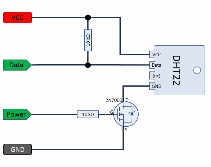
The voltage drop on the 2N7000 MOSFET is very small so the sensor is still working.
The DHT Element recognizes a unresponsive sensor that war working before and will turn off operation using the term() function.
If this happens during a sensor data read and the restart property is set to true the sensor is switched on again and after the warmup time has passed another data read try is started.
If failing repeats the sensor is switched off completely but can be restarted by another start action.
Implementation Details
As the sensor has a builtin sensor period of 0.5 to 2 seconds depending on the model it doesn’t make sense to read the values from the sensor more frequently.
See Also
-
DataSheet: https://www.sparkfun.com/datasheets/Sensors/Temperature/DHT22.pdf and https://cdn-shop.adafruit.com/datasheets/Digital+humidity+and+temperature+sensor+AM2302.pdf
-
A regular reset of the sensor also may be required when sensor readings are ´jumping´: https://forum.arduino.cc/index.php?topic=355137.0