Radio Example
The radio example can be used with any board that has a 4MByte Flash memory, a FM radio receiving board, a display and a rotary encoder with button.
In addition some wiring for amplifier and speaker or headphone connectors are required to create a full functional and remote controllable radio.
Setup the development environment and board
If this is the first time you use an ESP8266 board, some instructions on how to setup your development environment can be found here:
Step by Step setting up a development environment
There are some options in uploading the required software and registration on the network that s described here:
Step by Step Bring your device to work
This includes:
- Upload the sketch and Web UI
- Connect to the network
- Upload the Web UI files
After flashing the software and the web files the web interface is fully functional but not yet configured.
To ensure that all tools work as expected the Standard example should be used first.
Components for the Radio Example
By default the radio example shows how to build a internet connected device that has a dedicated element for controlling a RDA5807 FM radio chip and a TPA2016 chip that is a stereo amplifier with a volume control.
There are other chips supported by the radio library and some of them also provide volume control. To re-configure the example for SI473x chips see below.
The used components and the principle wiring can be seen in this block diagram:
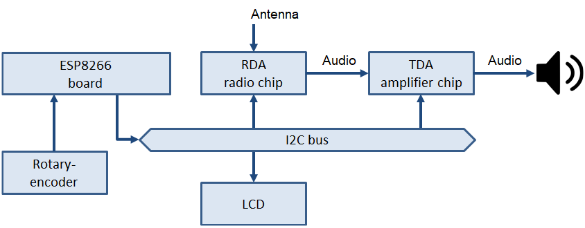
Wiring
The chips and the LCD all are connected using the I2C bus. This is used to drive the display and to control the radio and the amplifier functionality.
The rotary encoder is directly connected to the ESP8266 board.
The audio signals are analog and must be connected from the radio chip to the amplifier board. The speakers are connected to the amplifier board and the antenna to the radio board.
The following table contains all signal lines including the pin numbers:
| Signal | ESP8266 | LCD | Radio | Amp |
|---|---|---|---|---|
| I2C Data | D2 | Data | ||
| I2C Clock | D3 | CLK | #4 | #5 |
| VCC 3.3 | ||||
| VCC 5 | ||||
| GND | GND | GND | #4 | #5 |
Pictures
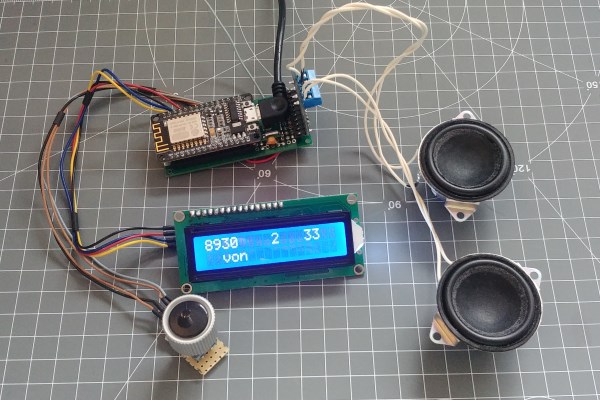
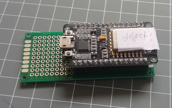
- The board and other hardware required for this example.
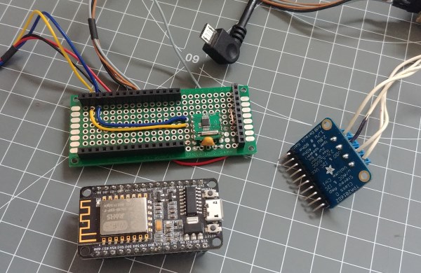
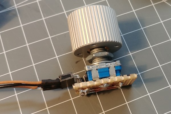
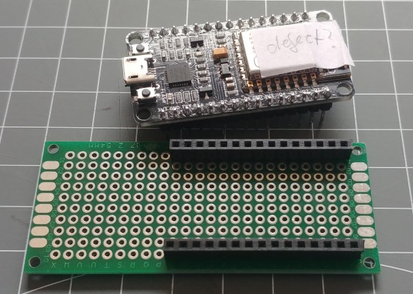
- The unconnected main board and amplifier board.
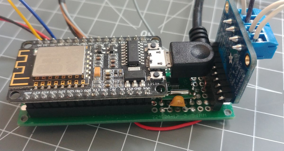
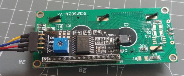
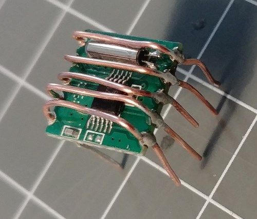
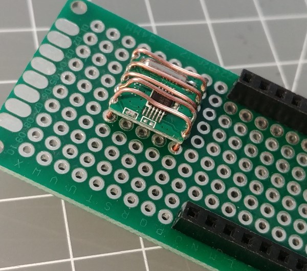
- Closer picture of the FM chip.
Board and Hardware to build the example
The following hardware is required for building all of this example:
- A NodeMCU board with ESP8266
- A radio chip like the RDA5807 that can receive FM and is controllable using the I2C bus
- A mobile phone headset (at minimum) or
- An amplifier and speakers.
- The TPA2016 amplifier chip is supported as well by this example
- Some buttons for input or a rotary encoder
- A display like the LCD
The element configuration that is used in this example are:
- rotary encoder or digitalin element
- menu element
- value elements
Power supply
I strongly propose to add a separate power source for the amplifier and the radio chip and not use the power from the Esp8266 board. The USB bus cannot provide much power and the noise on the USB power is usually bad for audio.
You also risk to burn the Regulator on the ESP board.
Elements in use
The elements that come with the example code are
- radio element
- TPA2016 element
These elements also show how elements can be implemented together with the sketch and are extending the capabilities of the device without the need to include them into the library.
Using a Rotary encoder
Using a rotary encoder is a good option to combine a twist and push input using 3 digital inputs to achieve a good usability.
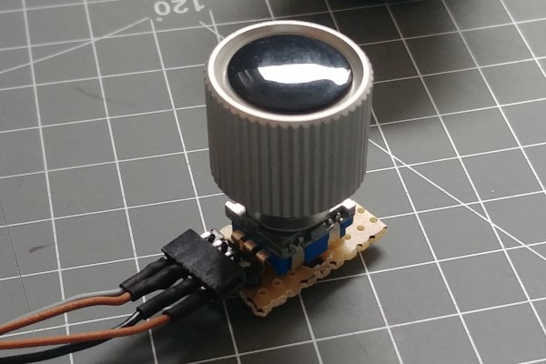
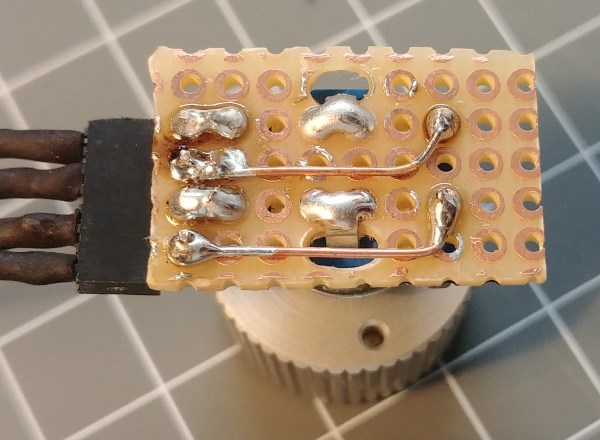
In the pictures you can see how the encoder is connected using a self-made PCB that provides a connector for later easy assembling. The connector has the push button and the 2 rotary signals all closing to a common ground signal.
When using the closing to ground approach the builtin pull up resistors of the chip can be used instead of a external resistor.
- push-button => D7
- rotary1 => D6
- ground => GND
- rotary2 => D5
When the turn is in the wrong direction you just have to switch the two rotary signals.
Alternative use up and down buttons
???
Long press the buttons to create repeated up and down actions.
???
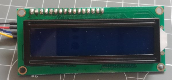
Using the LCD
The LCD is one of the standard display types that is used in many Arduino solutions. Here a backpack is added to allow using the LCD display on the I2C bus.
The LCD uses 5V power but accepts 3.3 V signals in the I2C bus.
- GND => GND (black)
- VCC => VIN (red) (the 5V directly connected to the USB adapter)
- SDA => D2 (blue)
- SCL => D1 (yellow)
The text on the display is using several displaytext elements to show the actual values of frequency, volume and RSSI.
The text in the second line is used by the menu element and for showing the station name from RDS.
Base PCB
I do not need many radios so I decided to use a prototype PCB as the base. Just large enough to hold all mechanically together.
Radio board
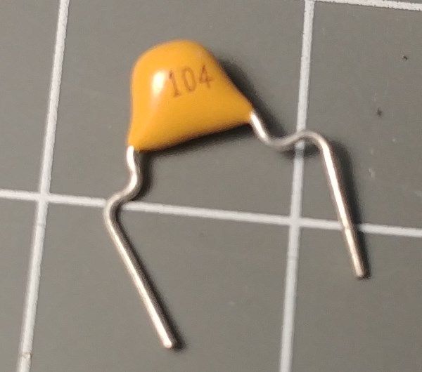
The RDA radio board is not following the typical 2.54 grid but has 2mm spacing connectors. By using the wires the way you can see on the pictures the board can be soldered to the base PCB. The wires on top are still visible during assembly for robustness and are later cut away (before applying power). I added a 100nF capacitor next to the radio.
// http://lcddevice/$board/radio/r?volume=1
// http://lcddevice/$board/radio/r?volume=12
// http://lcddevice/$board/board/0?loglevel=1
// http://lcddevice/$board/radio/r?softmute=0
// http://lcddevice/$board/radio/r?softmute=1

// http://lcddevice/$board/value/frequency?value=10390
// http://lcddevice/$board/value/frequency?value=8930
// http://lcddevice/$board/value/frequency?value=9560
// http://lcddevice/$board/value/frequency?value=9440
Example configuration
{
  "rotary": {
    "0": {
      "description": "Rotary Input",
      "pin1": "D5",
      "pin2": "D6",
      "step": 1,
      "onchange": "value/frequency?up=$v"
    }
  },
  "digitalin": {
    "0": {
      "description": "vol up",
      "pin": "D7",
      "invert": "true",
      "pullup": "true",
      "onhigh": "value/volume?up=1",
      "onlow": "value/volume?up=1"
    }
  },
  "value": {
    "volume": {
      "min": 0,
      "max": 15,
      "value": 3,
      "onchange": "radio/r?volume=$v"
    },
    "frequency": {
      "min": 8700,
      "max": 10800,
      "step": 10,
      "value": 8930,
      "onchange": "radio/r?frequency=$v"
    }
  },
  "menu": {
    "0": {
      "loglevel": 2,
      "onValue": "device/0?log=menu-v:$v"
    }
  },
  "radio": {
    "r": {
      "description": "A Radio",
      "loglevel": 2,
      "volume": 0,
      "onVolume": "displaytext/v?value=$v",
      "onFrequency": "displaytext/f?value=$v",
      "onStationName": "displaytext/text?value=$v",
      "onRDSText": "device/0?log=text:$v",
      "onRSSI": "displaytext/rssi?value=$v"
    }
  },
  "displaytext": {
    "f": {
      "x": 0,
      "y": 0
    },
    "v": {
      "x": 8,
      "y": 0
    },
    "rssi": {
      "x": 12,
      "y": 0
    },
    "text": {
      "x": 0,
      "y": 1
    }
  }
}