BL0937 Element
The BL0937Element has been implemented to support single phase energy monitoring using BL0937, HLW8012 or HJL-01 chips that are used in some retail plugs and switches.
All of these chips work the same by sending pulse signals that represent voltage, current and power. They have the same chip layout and pins. As they directly work with the main power signals, only using some resistors to reduce high voltage and high current they are not intended to be used on DIY IoT devices. The HLW8012 is an older model while the HJL-01/BL0937 is a newer more stable version.
The chip is directly working on the power line signals by measuring voltages and current. This part of the chip is lined out in detail in the datasheet. From this measurements the chip creates 38 micro seconds pulses on 2 pins that need to be captured by the microprocessor.
These chips can monitor power consumption side by side to monitoring either current or voltage.
The timing of these impulses will be used to calculate the power consumption, actual current and actual voltage. A device specific factor needs to be provided for all the calculations.
Warning
- This warning is serious.
- Stay away from devices with contact to mains voltage.
- Never handle this module when connected to the mains voltage as the contacts are not safe.
- Uploading firmware to devices that have contact to mains voltage is dangerous.
- DO NOT connect the any device to the mains during flashing or while using the serial interface.
- You may kill your computer and yourself.
- When you are making these kind of projects you really need to know what you are doing.
- I have warned you, do not blame on me.
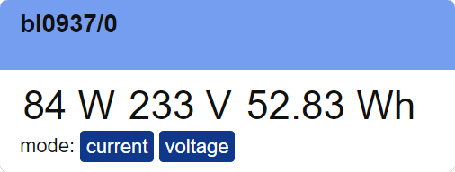
Web UI for the BL0937 Element
There is a dedicated card for this element available that shows the actual measured values and can switch between voltage and current mode.
Element Configuration
The following properties are available for configuration of the element:
selpin* – Specifies the GPIO pin that is used to select current or voltage mode.
cfpin* – Specifies the GPIO pin that is used to capture the cf signal from the chip for power consumption.
cf1pin* – Specifies the GPIO pin that is used to capture the cf signal from the chip for current or voltage.
mode – specifies wether the current or the voltage mode should be used.
cycletime – The cycletime defines the time in milliseconds that is used to collect impulses. The default is set to 2 seconds (2000 milliseconds) good for load > 10W. When having lower loads this time may be set to use longer time to count impulses.
powerfactor – This factor defines pulse density to power in W.
currentfactor – This factor defines pulse density to current in mA.
voltagefactor – This factor defines pulse density to voltage in V.
poweradjust – This action uses the given power value to calculate the power factor.
currentadjust – This action uses the given current value to calculate the current factor.
voltageadjust – This action uses the given voltage value to calculate the voltage factor.
onVoltage – These actions are emitted by the element when a new voltage value was measured.
onCurrent – These actions are emitted by the element when a new current value was measured.
onPower – These actions are emitted by the element when a new power value was measured.
onEnergy – These actions are emitted by the element when a new energy value was measured.
From the base element implementation the following properties are available for configuration:
title – Caption text for the element. Used by the element specific cards on the dash boards.
description – A line of text that gives a short description of the device used in the web UI.
room – The location of the device.
loglevel – This property holds the element specific log level. The default value is LOGGER_LEVEL_ERR == 1.
startup – This property can be used to start the element using a different initialization phase. Possible values are “sys”, “net”, “time”. See The Startup sequence.
* These properties are mandatory
Configuration Example
This example shows how to configure this element:
{
  "bl0937": {
    "0": {
      "loglevel": 2,
      "cycletime": "1000",
      "selpin": "D6",
      "cfpin": "D1",
      "cf1pin": "D2",
      "mode": "voltage",
      "powerfactor": "1346829.38",
      "currentfactor": "1346829.38",
      "voltagefactor": "1346829.38",
      "onpower": "displaytext/p?value=$v"
    }
  }
}
Element State
The following properties are available with the current values at runtime
active – Is set to true when the Element is active.
cycletime – The actual cycletime for counting pulses.
mode – The actual mode for cf1 pulses.
power – The actual power value.
powerfactor – The actual used factor.
current – The actual current value when current mode is active.
currentfactor – The actual used factor.
voltage – The actual voltage value when voltage mode is active.
voltagefactor – The actual used factor.
energy – The actual voltage value when voltage mode is active.
Example State
{
  "bl0937/0": {
    "active":"true","cycletime":"1000","mode":"voltage",
    "power":"120","powerfactor":"1346829.38",
    "current":"435","voltagefactor":"129059.00",
    "energy":"52.83"
  }
}
Supported retail devices
There are some devices available using the ESP8266 processor and one of these energy monitoring chips:
- Sonoff POW Power Monitoring Switch
- BlitzWolf BW-SHP6 10A
- BlitzWolf BW-SHP6 15A
- Gosund SP111 Power Monitoring Plug
- BlitzWolf BW-SHP2 Power Monitoring Plug
- Nous A1, Nous A1T Smart WiFi Socket
Many of them are manufactured by Tuya and re-branded.
When you find your device in the Template list at https://templates.blakadder.com/all.html and its functionality mentions a BL0937 or HLW8012 chip like the https://templates.blakadder.com/gosund_SP111.html it is likely to be supported by this element.
Here you can also detect the GPIOs used connecting to the chip (SEL, CF, CF1).
Calibration
Most devices with these chips differ in the accuracy of the pulses. Therefore to get good results the default factors should overwritten in the configuration.
The get the device specific factors a reference load is required where the power consumption is known or use another good power measuring tool. The best results are given by pure resistor loads like classic light bulbs. Here a 100W light is used.
- call http://socket01/api/state/bl0937/0?cycletime=5000 to create a more precise pulse monitoring 5 sec cycles can be used.
- call http://socket01/api/state/bl0937/0?mode=voltage
- Switch on and wait some cycles (30secs).
- call http://socket01/api/state/bl0937/0?poweradjust=100 to adjust the powerfactor
- call http://socket01/api/state/bl0937/0?voltageadjust=226 to adjust the voltagefactor
- calculate the current in mA using the formula current = watt/voltage*1000
- call http://socket01/api/state/bl0937/0 and see the powerfactor and voltagefactor
- call http://socket01/api/state/bl0937/0?mode=current
- Wait some cycles (30secs).
- call http://socket01/api/state/bl0937/0?currentadjust=435
- call http://socket01/api/state/bl0937/0 and see the currentfactor
(you may use your device name and adjust the id of the bl0937 element. Here just 0 was used.)
enter the 3 factors into the configuration.
How the chip works
To meassure voltage and current the chips are connected via resistors to the main power signals. A special load resistor is required to measure the current and the resulting voltage over the resistor is then probed by the chip.
Voltage or current can be measured alternatively but the energy monitoring is active permanently.
The result of the measurement are impulses on the CF (energy) and CF1 (Voltage or Current) pins.
The BL0937 Element captures these pulses using the nanosecond timer to calculate the values.
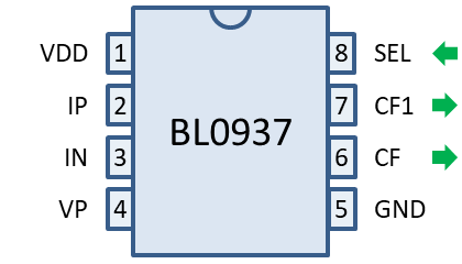
| Pin | symbol | Description |
|---|---|---|
| 1 | VDD | Chip power supply (+3.3V): |
| 2, 3 | IP, IN | Input of the current channel with a maximum differential voltage of ±50mV. |
| 4 | VP | Input of the voltage signal with a maximum of ±200mV. |
| 5 | GND | Chip ground. |
| 6 | CF | Actual power frequency pulse output. |
| 7 | CF1 | Actual current or voltage high-frequency pulse output. |
| 8 | SEL | current / voltage output selection |
The pins CF and CF1 produce signals:
SEL signal - This signal is given by the element to the chip to switch between voltage and current measurement. It can be switched by the
modeproperty of the element.CF signal - This signal emits pulses where the frequency is proportional to the power consumption. The maximal frequency is about 6,78 KHz when the limit of the sensor is reached.
CF1 signal - This signal emits pulses where the frequency is proportional to the current or voltage value to be measured.
See also
Here are some links related to this chip and flushing a plug device.
-
https://forum.iobroker.net/topic/26468/gosond-sp-111-v1-1-neue-platine
-
https://blog.moneybag.de/review-gosund-sp-111-die-noch-kleinere-wlan-steckdose/
-
https://www.malachisoord.com/2019/11/24/flashing-custom-firmware-on-a-gosund-sp111/
-
How the chip works: https://www.itead.cc/blog/introducting-the-hlw8012-ic-in-the-sonoff-pow
-
A Arduino Library : https://github.com/xoseperez/hlw8012
-
Tasmota implementation: https://github.com/arendst/Tasmota/blob/development/tasmota/xnrg_01_hlw8012.ino
-
Another implementation https://github.com/MacWyznawca/HLW8012_BL0937_ESP
-
Tasmota supported devices https://templates.blakadder.com/all.html