DisplayMAX7219 Element
The DisplayMAX7219 Element implements a larger display by using LED 8x8 led displays matrixes based on MAX7219 controller chips.
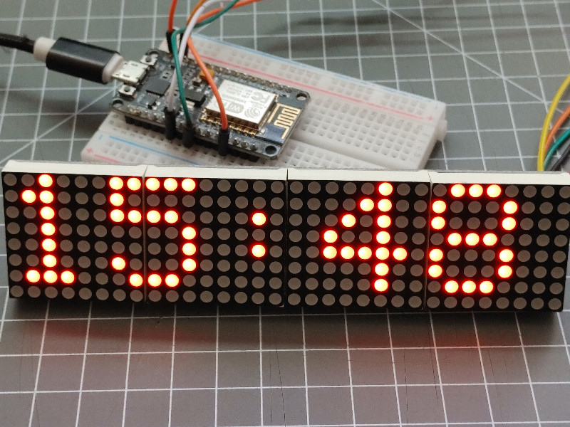
This display implementation supports LED matrix setup with 1 line of 8x8 modules using the GFX 8-pixel font.
The DisplayMAX7219 Element needs to be configured for using the standard SPI interface and specifying the select GPIO pin.
The parent class DisplayElement implements the configuration that is passed to the adapter implementation to initialize the hardware and canvas.
The DisplayAdapterMAX7219 uses the canvas class from the Adafruit_GFX library to create an in-memory picture that can be shifted to the display when drawing of the output element has finished.
Connectivity
The MAX7219 based displays uses a SPI based data interface sending data out only. On ESP8266 the standard SPI interface is used. On ESP32 the VSPI interface is used.
The display must use it’s own chip select (CS) line.
| MAX7219 | ESP8266 | ESP32 | max7219 |
|---|---|---|---|
| VCC | VCC | VCC | +5V, VCC from USB |
| GND | GND | GND | Common Ground |
| DIN | GPIO13(D7) | GPIO23 | SPI-MOSI, Data to Matrix |
| CS | GPIO0(D3) | GPIO05 | CS, Select signal |
| CLK | GPIO14(D5) | GPIO18 | SPI-CLK, Clock |
See also Using the SPI bus
Element Configuration
The following properties are available for configuration of the element:
| Property | Description |
|---|---|
spiCS |
Specifies the spi component select pin of the display. |
height |
The height of the display. 32 or 64 |
Configuration Example
The configuration of a display is given by the provided hardware and should be configured in the env.json file.
This example shows how to configure this element:
{
  "DisplayMAX7219": {
    "0": {
      "width": 32,
      "height": 8,
      "brightness": 10,
      "spiCS": "D3"
    }
  }
}