PMS Element
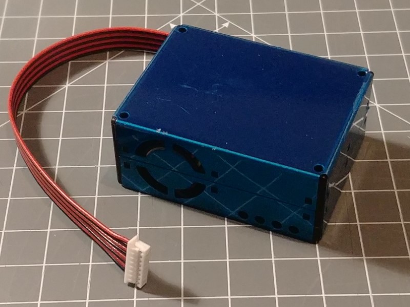
The PMSElement allows using the laser based air particle and pollution sensor PMS5003 from plantower to report the number of micro particles in the air.
This Element is not included into the standard firmware but can be included by defining:
#define HOMEDING_INCLUDE_PMSin the element register section of the sketch.
About the sensor
The particles with the size of 2.5 µm are too small to be visible individually but when present in high concentration can be seen as dust or smog.
This fine dust particulates have the ability to penetrate deep into the lungs causing some bad disease. Some of them come from automotive pollution.
This sensor has its own onboard processor driving a laser based particle detection in a constant flow of air. It communicates the results of measurement every second using a 9600 baud serial interface.
The PMS5003 device should be attached using the following connections:
ESP8266 PMS5003 +5V pin1, VCC (black) GND pin2, GND (red) +3.3V – 10k – pin3 SET D5 (TX) pin4 RXD (red) D6 (RX) pin5 TXD (black) +3.3V – 10k – pin6 RESET
(as suggested by the plantower-pms5003-manual_v2-3.pdf)
The 10k resistors are not strictly required as the pins seem to be internally pulled to VCC as well.
Sensor Interface
Data from the sensor is passed using a serial protocol with 9600 baud.
Inside the ESP8266 chip only 1 UART / Serial port is available that can receive and send data using builtin hardware and is usually connected to the USB bridge. The second UART implementation can only transmit data.
Therefore the SoftwareSerial library that is part of the ESP8266 board implementation for Arduino is used to communicate with another serial counterpart in the sensor.
The sensor sends data probe results quiet frequently and can be started and stopped by a command sent to the sensor.
Using the element configuration it is possible to take a current probe value every n seconds using the readtime configuration and combine multiple values by taking the average using the combine configuration.
Element Configuration
The following properties are available for configuration of the element:
pinrx - The property specifies the pin of the board to receive data from the sensor. This property must be specified.
pintx - The property specifies the pin of the board to send data to the sensor. This property must be specified.
readtime - The time between capturing 2 probes from the sensor.
onValue - These actions are send when the value from the sensor has changed.
From the base element implementation the following properties are available for configuration:
title – Caption text for the element. Used by the element specific cards on the dash boards.
description – A line of text that gives a short description of the device used in the web UI.
room – The location of the device.
loglevel – This property holds the element specific log level. The default value is LOGGER_LEVEL_ERR == 1.
startup – This property can be used to start the element using a different initialization phase. Possible values are “sys”, “net”, “time”. See The Startup sequence.
Example configuration
"pms": {
  "pm25": {
    "pinrx": "D6",
    "pintx": "D5",
    "readtime": 300,
    "description": "read out pm25 sensor",
    "onvalue": "log/pm?value=$v"
  }
}
Diagnostic example
The checkPMS example sketch on git … can be used to verify an existing connected sensor for working correctly. It requires no special library and logs the raw data and some calculated values to the serial line for analysis.
You can use this sketch to verify that the sensor is communicating correctly in the standard mode.
See also
- https://www.epa.gov/pm-pollution/particulate-matter-pm-basics
- Some insights to accuracy of the sensors and pictures from a tear-down: https://aqicn.org/sensor/pms5003-7003/de/
- http://raphuscucullatus.blogspot.com/2017/08/pms5003-will-schlafen.html?m=1
- https://ourairquality.org/index.php/build-an-air-quality-monitor/
- https://github.com/ourairquality
- http://www.aqmd.gov/docs/default-source/aq-spec/resources-page/plantower-pms5003-manual_v2-3.pdf
- http://luftdaten.info/
- https://github.com/avaldebe/PMserial/blob/master/README.md