MAX7219 Element
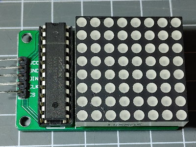
The MAX7219Element enables using a single 8*8 dot display or a single 8 digit 7-segment display by using a MAX7219 driver chip. For dot matrix displays using multiple chips the DisplayMAX7219 Element offers full display support.
The MAX7219 is using the SPI interface and protocol to receive commands and data.
It can either display a 8*8 bit pattern on a dot matrix or a numeric value with 7 segment display.

Element Configuration
The following properties are available for configuration of the element:
value - The value given as an input to the element can be either a 8 byte value using the format 0x1122334455667788 in 8x8 mode or a string with a number including decimal point when in numeric mode
clear - a clear action will disable all leds.
cspin - The pin for the cs signal line.
brightness - The brightness of the display in range 0…16.
mode - 8x8 or numeric.
Configuration Example
This example shows how to configure this element:
{
  "max7219": {
    "0": {
      "title": "wordclock matrix",
      "cspin": "D3",
      "brightness": 2,
      "mode": "8x8"
    }
  }
}
Connecting the MAX7219
The MAX7219 is using the SPI interface and protocol to receive commands and data. There is no data sent by the MAX7219.
Here D3 is used for selecting (enabling) the chip.
| ESP8266 | ESP32 | MAX7219 |
|---|---|---|
| D3 | 5 | CS |
| D5 (SCK) | 18 (SCK) | CLK |
| D6 (MISO) | 19 (MISO) | not connected |
| D7 (MOSI) | 23 (MOSI) | DIN |
| +5V | +5V | VCC |
| GND | GND | GND |
State
The following properties are available with the current values at runtime
active - Is set to true when the element is active.
Example State
{
  "max7219/0": {
    "active":"true",
    "mode":"8x8",
    "brightness": "5"
  }
}
See also
- DisplayMAX7219 Element
-
- General info on SPI usage: https://diyi0t.com/spi-tutorial-for-arduino-and-esp8266/
-