LilyGO T-Display-S3
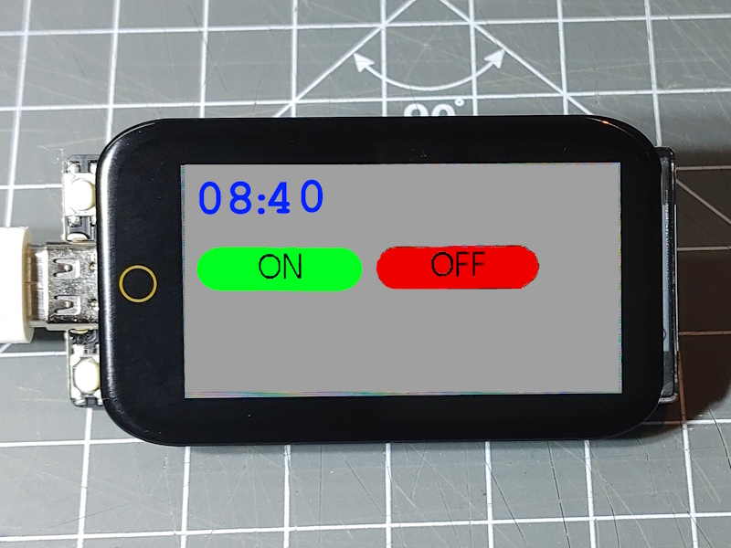
The LilyGO T-Display-S3 board has an integrated TFT color display with optional capacitive touch and a USB-C type connector.
The T-Display-S3 is a ESP32-S3 based development with a 1.9" IPS LCD color touch screen and two separate momentary buttons. Communication to the display is using a fast 8 bit interface. The USB-C board is supported by the ESP32-S3 chip.
Arduino Board Configuration
The board is known in the list of predefined board configurations for esp32 by espresif. It can be used with the following Arduino settings:
- Package: esp32 by Espressif
- Board: LilyGO T-Display-S3
The following board settings can be used:
- JTAG Adapter: Disbled
- Arduino Runs On: Core 1
- Events Runs On: Core 1
- USB Mode: Hardware CDC amd JTAG
- USB CDC On Boot: Enabled
- USB Firmware MSC on Boot: Disabled
- USB DFU on Boot: Disabled
- Upload Mode: UAT0 / Hardware CDC
- Partition Scheme: 16M Flash (3MB APP/9.9MB FATS)
- Core Debug Level: None
- Erase All Flash: Disabled
For the Arduino-CLI the following boardname and build properties can be used:
fqbn = "esp32:esp32:lilygo_t_display_s3"
properties = "JTAGAdapter=default,LoopCore=1,EventsCore=1,USBMode=hwcdc,CDCOnBoot=cdc,MSCOnBoot=default,
  DFUOnBoot=default,UploadMode=default,PartitionScheme=app3M_fat9M_16MB,DebugLevel=none,EraseFlash=none"
Display ST7789
The display is a IPS type TFT display using the ST7789 driver chip on the SPI bus. It is
supported by the GFX Library for Arduino.
The board supports a display resolution of 170*320 pixels in 64k colors in RGB565 addressing.
The background lightning can be adjusted using PWM based LED control on pin GPIO38.
Touch CST816
The touch screen is using the CST816 chip that is supported by the Display TouchCST816 Element. Is is using the i2c bus as an interface and the SCL and SDA pins must be specified in the device element configuration.
The touch controller goes beyond the graphics surface and when touching the soft button marked with a circle below the display the touch controller reports a touch event on location ???
Buttons
The board is equipped with 3 momentary buttons:
- The reset button is reachable at the side of the main board.
- The Boot button is connected to GPIO0 as usual. It is located ??? left to the USB-C port.
- THe Key Button is connected to GPIO14 and is located ??? left to the USB-C port.
The Key button and the Boot button can be used for functional purpose when the device has booted.
Power
The board can be powered through the USB-C connector. It does not support the complete USB-C specification, especially not the USB-C voltage negotiation protocol and a USB2.0 USB-A to USB-C cable must be used.
The board can run by using the power from a 3.7 V LiPo battery pack attached to the JST-GH 1.25mm 2pin connector on the board. There is a LiPo charger chip that loads the battery.
The time the device can run on batter power supply depends on the given LiPo capacity. As the display is the most power consuming part of the device this is switched off on battery mode (no power provided by USB-C).
The battery mode can be controlled by 2 pins:
GPIO15 – This pin can enable the power to the display on battery. When the pin is pulled high the 3.3 volt is given to the display and the green LED on the board. A Digital Output Element can be used to control this signal. It takes a few milliseconds until the display is really on.
There is a recipe below that uses the menu touch button to trigger a timer so the display is on for some seconds when needed.
GPIO4 – This pin can be used to messure the current battery voltage. When in battery mode and GPIO is not enabling the display power the voltage is not enable. This is in contrast to the existing board schema.
{
  "analog": {
    "bat": {
      "pin": "4",
      "title": "Battery power",
      "readtime": "1s",
      "hysteresis": "1",
      "onvalue": "device/0?log=bat-$v"
    }
  }
}
Example env.json Device Configuration
{
  "device": {
    "0": {
      "name": "tdisplays3",
      "title": "LilyGO T-Display-S3",
      "description": "LilyGO T-Display-S3R8 with capacitive touch",
      "loglevel": "2",
      "logfile": 1,
      "safemode": "false",
      "homepage": "/board.htm",
      "xcache": "etag",
      "i2c-SDA": "18",
      "i2c-SCL": "17",
      "battery_volt": "4"
    }
  },

  "ota": { "0": {} },

  "DisplayST7789": {
    "0": {
      "width": "170",
      "height": "320",
      "rotation": "270",

      "busmode": "par8",
      "buspins": "39, 40, 41, 42, 45, 46, 47, 48",
      "ips": 1,
      "rowOffset": 0,
      "colOffset": 35,
      "resetpin": 5,
      "lightpin": 38,
      "cspin": "6",
      "dcpin": "7",
      "wrpin": "8",
      "rdpin": "9",

      "color": "black",
      "border": "black",
      "background": "#cccccc"
    }
  },

  "DisplayTouchCST816": {
    "0": {
      "width": "170",
      "height": "320",
      "rotation": "270",
      "resetpin": 21,
      "interruptpin": 16
    }
  }
}
Enable the display on Battery mode
On battery mode the display will not get the VCC automatically. The GPIO15 port can be used to enable power for some time to save energy while not in use.
To enable the display even on startup the “digitalout/lcd” element must be configured before the display by using the system startup.
{
  "digitalout": {
    "lcd": {
      "pin": "15",
      "startup": "sys",
      "title": "Display Power control",
      "value": "1"
    }
  }
}
The touch controller element
Here the touch event from the touch element that is triggered on any touch will start the timer that enables GPIO15 for 8 seconds.
{
  "DisplayTouchCST816": {
    "0": {
      ...
      "ontouch": "timer/lcd?start=1"
    }
  },
  "timer": {
    "lcd": {
      "loglevel": "2",
      "title": "Display Power timer",
      "pulsetime": "8s",
      "title": "timer/lcd",
      "onvalue": "digitalout/lcd?value=$v"
    }
  },
  "digitalout": {
    "lcd": {
      "pin": "15",
      "title": "Display Power control",
      "value": "1"
    }
  }
}
Use the Menu touch button
Below the display there is a circle drawn on the display that can be touched. This creates a touch event at position 85/-40. When the display and touch is rotated, the coordinates must be adapted.
A displaybutton outside the visible display box can be declared to capture these touch events to trigger an action:
{
  "displaybutton": {
    "menu": {
      "x": "85",
      "y": "-40",
      "w": 1,
      "h": 1,
      "onclick": "device/0?log=menu"
    }
  }
}
See Also
-
https://github.com/teastainGit/LilyGO-T-display-S3-setup-and-examples
-
http://www.lilygo.cn/prod_view.aspx?TypeId=50062&Id=1400&FId=t3:50062:3