LilyGO T-Dongle S3
The LilyGO T-Dongle-S3 board has a USB stick layout including a TFT color display, a APA102 LED, a input button and SD card slot.
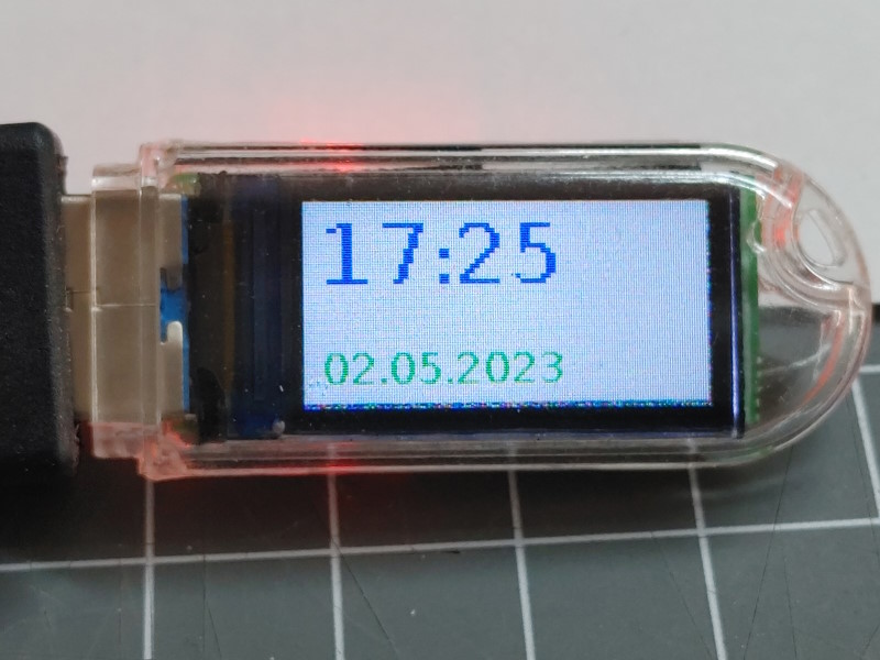
This panel including advanced graphic features is supported by the HomeDing Display Example.
The following features are available on this board.
This board is equipped with:
- ESP32-S3 processor
- 16 MByte Flash in QIO mode
- 80 * 160 px based on ST7735: 16-bit color, SPI
- SD card slot
- A momentary Input button
- Color LED
ST7735 based display
The built-in display based on the ST7735 chip has a 80 * 160 resolution and is using the following pins:
| function | ESP32 pin |
|---|---|
| CS | GPIO4 |
| MOSI | GPIO3 |
| CLK | GPIO5 |
| DC | GPIO2 |
| Reset | GPIO1 |
| LED | GPIO38 |
As this display is using the available resolution of the ST7735 (132 x 162) only partally a column offset of 26 and a row offset of 1 must be configured.
This display is supported by the Arduino_GFX library mentioned as “096-ips-lcd-80x160”.
The complete configuration of the DisplayST7735 Element can be found below.
See also https://github.com/moononournation/Arduino_GFX/wiki/Display-Class#096-ips-lcd-80x160
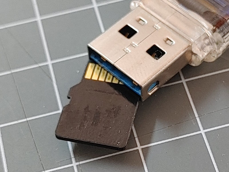
Faster SD Card
The SD Card inside the USB connector is connected directly to the ESP32-S3 processor using the MMC interface. As the ESP32-S3 processor offers flexibility in using custom defined pins a pin configuration (see below) must be given:
| function | ESP32 pin |
|---|---|
| CLK | GPIO12 |
| CMD | GPIO16 |
| D0 | GPIO14 |
| D1 | GPIO17 |
| D2 | GPIO21 |
| D3 | GPIO18 |
Input Button
The input button on the back of the stick pulls the esp32-pin 0 down when pressed.
| function | ESP32 pin |
|---|---|
| Button | GPIO0 |
Don’t configure this button in the device configuration to start the config mode as it is set to active LOW
Color LED
The color LED on the backside is a APA102 LED supported by the APA102 Element.
Data and Clock lines are connected on these pins:
| function | ESP32 pin |
|---|---|
| Data | 40 |
| Clock | 39 |
Arduino Board Configuration
To compile for this board in Arduino the following settings for the board can be used:
- ESP32S3 Dev Module
- JTAG Adapter disabled
- PSRam disabled
- Flash Mode QIO 80 MHz
- Flash Size: 4MB
- USB Mode Hardware CDC and JTAG
- USB CDC On Boot: Enabled
For the Arduino-CLI the following boardname and build properties can be used:
fqbn = "esp32:esp32:esp32s3"
properties = "JTAGAdapter=default,PSRAM=disabled,FlashMode=qio,FlashSize=16M,
  LoopCore=1,EventsCore=1,USBMode=hwcdc,CDCOnBoot=cdc,MSCOnBoot=default,DFUOnBoot=default,
  UploadMode=default,PartitionScheme=default,CPUFreq=240,UploadSpeed=921600,DebugLevel=none,EraseFlash=none"
Board configuration
The following env.json configuration can be used for this board and contains settings for
- The device in general
- The ST7735 based display
- A value and pwm output to control the display brightness
- The digital input signal definition for the button on the back.
{
  "device": {
    "0": {
      "name": "dongle-s3",
      "description": "ESP32-S3 based USB stick.",
      "title": "T-Dongle-S3",
      "loglevel": 2,
      "led": "38"
    }
  },

  "DisplayST7735": {
    "0": {
      "description": "Display",
      "width": "80",
      "height": "160",
      "rotation": 270,
      "colOffset": 26,
      "rowOffset": 1,
      "ips": 1,

      "busmode": "spi",
      "spiClk": 5,
      "spiMosi": 3,
      "spiDC": 2,
      "spiCS": 4,
      "resetpin": 1,

      "background": "black"
    }
  },

  "digitalin": {
    "pin": {
      "description": "Momentary button",
      "pin": "0",
      "inverse": "1",
      "pullup": 1
    }
  },

  "pwmout": {
    "displayled": {
      "title": "Backlight",
      "description": "Display Backlight",
      "pin": "38",
      "range": "255",
      "inverse": "1"
    }
  },

  "apa102": {
    "led": {
      "description": "RGB color LED",
      "datapin": 40,
      "clockpin": 39,
      "count": 1,
      "loglevel": 2,
      "duration": "4s"
    }
  },

  "sdmmc": {
    "0": {
      "mmcD0": "14",
      "mmcD1": "17",
      "mmcD2": "21",
      "mmcD3": "18",
      "mmcCLK": "12",
      "mmcCMD": "16"
    }
  }
}
Diag and chipinfo output
**Info**
DeviceName: dongle-s3
Build Date & Time: Jan 26 2024T08:09:56
State: []
Mac-address: F4:12:FA:41:xx:xx

no i2c bus.
Chip Infos:
model: esp32s3(9)
features: 00000012
2.4GHz WiFi
Bluetooth LE
cores: 2
revision: 0
Flash: Size: 16384 kByte
Mode: QIO(0)
Speed: 80000000
PSRAM: Size: 0 kByteSee also
- Color Display based on ST7735
- APA102 Element
- SD Card
- https://www.lilygo.cc/products/t-dongle-s3
- https://github.com/Xinyuan-LilyGO/T-Dongle-S3